
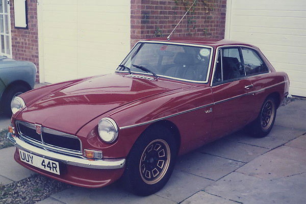
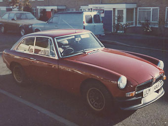
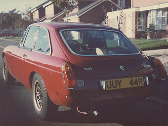
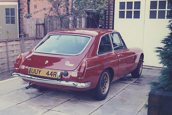
Barry Yardley's 1977 MGB with Rover 3500 V8
Roger Parker describes building Barry's fuel-injected MGB-V8 swop
as published in British V8 Magazine, Volume XVI Issue 1, May 2008Note: This article was originally written in 1985 by Roger Parker for his friend Ken Smith, who intended to include it in a book for MGB V8 enthusiasts. Better late than never, British V8 is proud to be publishing Ken's collection of notes. Twenty-three years have passed, yet we feel this article is still quite relevant and interesting!
Owner: Barry Yardley
City: Minworth, Sutton Coldfield, UK
Model: 1977 MGB
Engine: Rover 3500 V8
Conversion by: Roger Parker and Barry Yardley
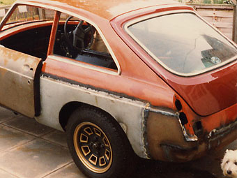
This is the story of the construction of an MGB GT V8 from a bare shell to running
vehicle being used on the road. It is a project undertaken by a fellow MG nut,
Barry Yardley and myself. The car is Barry's daily transport and as such it has
to cope with the Birmingham rush hour traffic, this means that the car has to be
totally practical and reliable in normal use as well as being reasonably easy on
petrol. The final mechanical specification has some major differences from that of
the original factory MGB GT V8 which enhance both performance and reliability.
It also has some compromises which are not the perfect match but are dictated by
costs and availability.
I think most MG enthusiasts would agree that the original MGB GT V8 provided a
level of performance and refinement that as excellent for its day, especially so
when all the financial and other restrictions imposed on it are considered.
This in my view left two particularly obvious areas which could be improved on.
These were the gearbox and engine power, both of which have related reasons for
their standard specification. Since 1975 there have been many developments in car
design, to the point that we now have the situation where many mass produced
sports saloons provide power outputs very close to the 157 bhp of the original
V8. In addition, other developments have enhanced their performance further so
that with less power than the V8 these cars can provide similar performance.
Just look at the new Astra GTE, 115bhp - 126 mph - 8 sec 0-60mph. However at
the moment there is one area where the V8 still wins hands down, that is
torque, and it is an area which can be further enhanced.
Our project car was started over three years ago. Initially the plan was to
rebuild an accident damaged MGB GT and to retain the 4-cylinder engine but to
convert the body to accept a V8 transplant as a bolt in operation later. The
4-cylinder engine would have been uprated to a similar specification to my own
2-litre overbored 'B' series engine. This plan was amended at an early stage
to go straight to V8 for a variety of reasons. At this time, a great deal of
planning was required before commencing the actual build, also we had a large
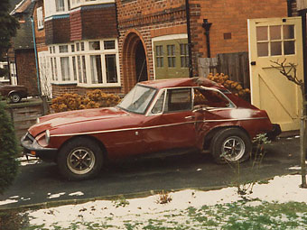
number of components that could be used. These included (a) a written-off 1977
rubber bumper GT which had received a very substantial side impact when it tried
to move a wall. (The wall won!) This was bought in this condition and was
mechanically complete. (b) An early 10.5:1 compression ratio Rover 3.5-litre V8
engine which required little rebuilding due to its previous use and lack of road
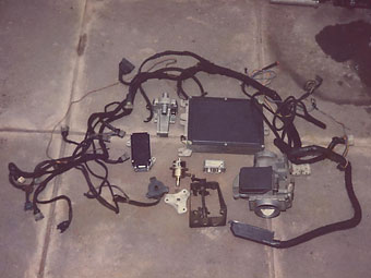
mileage and (c) a complete Federal specification fuel injection set up that was
intended for the ill fated SD1's sent to the United States. All of these components,
when married together, had the potential to make an interesting car.
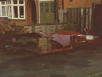
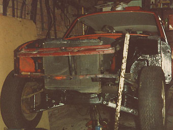
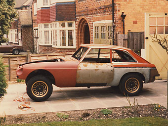
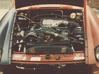
The 1977 car was fortunately little damaged in the mechanical areas, however as can
be seen in the photo, the body was substantially bent. In addition the large amount
of hidden rust present in the shell made it impractical to reuse this body. The next
idea was to obtain a brand new body and convert it to the chrome bumper specification
as far as the exterior fittings were concerned. This would have been quite easy
with the bare shell and the great advantage would be that the new shell would have
the latest specification underbonnet area which would allow easy bolt in of the
mechanical components from the damaged car as well as allowing for the later conversion
to V8. Unfortunately at the time we were after a new shell the availability and
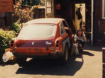
cost was not very attractive and accordingly the following route was taken. A 1970
standard chrome bumper shell was obtained and fully rebuilt in respect of all the
rust damage normally found in the MGB. In addition to these repairs a considerable
number of modifications were completed again with the later V8 installation in mind.
These modifications are detailed in the following paragraphs. It was at this time
that the decision was made to go straight to V8 specification mainly because of the
reduced complication involved in just building the car with one type of engine.
With the project simplified and the goal set, it now left a number of important
decisions to be made as to what components to use, both major and minor. Most
knowledgeable MG buffs will know that the major problem areas when fitting a V8
into the MGB centre round (1) which gearbox to use, (2) which induction setup to
use, (3) what exhaust manifolds and steering shafts to use, (4) what radiator to
use, and (5) how to fit an oil filter. These are the main areas for modification
and do not include the very many smaller problem areas usually only found when
you actually try and do the conversion. As I have already indicated we were in
possession of a number of items including an engine and a fuel injection system
which we wanted to use together. It was also our desire to have a completely
standard exterior body line with no ungainly bonnet bulges. Measurements taken
gave the impression that with this fuel injection, the standard bonnet could be
retained. For the remainder of the underbonnet components it was decided to
follow the standard MG V8 and use as many of the standard parts or pattern parts
as possible.
Moving on to the gearbox, this now presented additional problems. We were very
much aware that the torque capacity of the standard MG V8 gearbox was being
stretched with the standard MG V8 torque of some 198 ft lbs, so with the addition
of the fuel injection (and some more special modifications planned for the future)
the torque would rise by at least ten percent. We are now fortunate in that there
is a standard gearbox from the Rover SD I which has ample torque capacity and
the benefit of five gears so this was the gearbox that would be used. Also from
the same source would come the bell housing, flywheel and clutch. (No doubt if
the five speed box was available when the original MG V8 was being developed,
it could well have been used in the production car.) The use of the Rover gearbox
would then require changes to the propshaft, and for the best effect the rear
axle ratio would have to be changed. All of the preceding items would allow the
car to go very well and it would be appropriate to point out that the other
necessary areas for modification, namely the brakes and suspension had not been
overlooked and these areas would in fact be completed prior to the engine installation.
This gives a brief outline of the plans that we made and now I will detail the
build of the car in a number of separate sections each under a broad title.
The Body
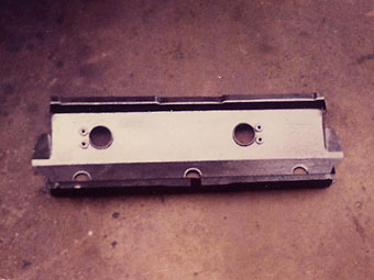
As has already been indicated, the original base car was a 1977 rubber bumper GT and the replacement shell was a 1970 chrome bumper GT. Anyone who knows these two model years will know that apart from the obvious external differences there are a huge number of other differences under the skin. Some of these would not be suitable in our project but a large number would be and they would be incorporated. The replacement shell was first repaired in the usual areas which was a very straightforward operation and is one which has received much previous coverage. Once this work was complete, work was started on the underbonnet area which was to be converted to the same specification as the 1977 donor shell. To this end we took a large number of measurements from the donor shell before cutting out various panels ready for reuse in the 1970 shell. The panels used were, (1) the bonnet platform, (2) the radiator mountings, (3) the bulkhead corners. Also the following new panels were bought, (1) two later style chassis mounted engine mounting brackets and (2) the later style oil cooler mounting platform (for the underslung cooler). Prior to refitting the salvaged panels they were all carefully separated from the unwanted metal that was cut off with them, and then they were shot blasted.
On the 'new' shell, the first job was to cut off the original engine mounting
brackets followed by the radiator mountings, followed by the bonnet locking platform
and its support and lastly the oil cooler tray support panel was cut off from
underneath. The measurements that we had previously taken from the donor shell
were then superimposed onto the new shell and marked. These were carefully
rechecked to ensure accuracy before the original oil cooler tray was cut out
from the back to match the later style of oil cooler tray. The remaining portion
of this tray then had the holes cut out to allow access to the oil cooler pipes
before the underslung reinforcement/cooler mounting was welded on.
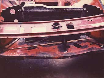
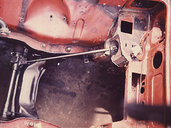
The next area for attack was the rear of the engine compartment and both bullhead
corners to be precise. These have to be modified on the earlier shell in order
to allow clearance to the V8 cylinder heads. The modification of the nearside
corner was very simple. The complete corner panel removed from the donor shell
was superimposed onto the new shell which allowed the corner to be marked and
cut out. The donor panel was then fitted to the shell and welded. In complete
contrast to the simple nature of the nearside panel, the offside panel was very
much more complicated as this corner also carries the lower steering column mounting
and this has to be accurately aligned. The way in which we tackled this was to fit
the complete steering assembly to the car by the mountings that were to remain and
then obtain alignment for the bulkhead corner in this way. Otherwise the corner was
fitted as per the nearside except that, prior to seam welding, the alignment was
further checked to ensure accuracy.
In the previous paragraph, I referred to the whole steering assembly being fitted so that the bulkhead corner could be aligned. The steering rack fitted without any problems but inside the cabin the upper column mountings are totally different from the earlier cars and require considerable further modification to fit. Our solution was to cut out the crossbrace and speaker panel as a complete unit from the donor shell and transfer it to the new shell. This crossbrace carries several mounting points for the later type of steering column and once fitted to the shell it allows the positions of the remaining upper mountings to be marked on the bulkhead area prior to cutting the new holes. The area where these mountings attach is mostly of a double skinned nature and this requires several access holes to be cut in the area as well as the holes for the mounting bolts. This is a somewhat fiddly job as it is best to cut away as little metal as possible for the access holes. The mounting bolts also used large flat washers to spread the loadings as much as possible.
Enjoying this article? Our newsletter is funded through the generous support of readers like you!
To contribute to our operating budget, please click here and follow the instructions.
(Suggested contribution is twenty bucks per year. Feel free to give more!)
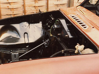
With the completion of the steering and bulkhead modifications the remaining underbonnet
modifications were of a much simpler and easier nature. The positions for the new engine
mountings and the salvaged radiator mountings were marked and checked before these items
were welded in. Then the bonnet locking platform which had previously been removed was
refitted and welded. The panel used was the one from the donor shell as it retains the
mounting holes for the factory type of electric cooling fans which we would be using.
Of course prior to the welding of this panel, all measurements were checked. We now had
an underbonnet area which is very similar to that of later cars and V8's. The only other
area we found required modification to fit the engine and gearbox was the front of the
transmission tunnel in the area under the nearside bulkhead corner. This required being
dressed lack an inch or so to give clearance to the bulkier bell housing of the
5-speed box.
Moving away from the engine compartment and into the transmission tunnel found that
very few changes were required to fit the gearbox. The top of the tunnel in the area
of the speaker mounting, when looking from underneath, has to be dressed upwards to
give clearance to the bulkier nature of the gearbox. The amount of clearance required
is only a small amount and it does not alter the shape of the transmission tunnel when
looking from inside. The only other mod is to the gearstick hole which his to be
enlarged at the rear by a small amount to allow selection of 2nd and 4th gears. No
other mods were found to be required to the body. The last area of body modifications
were in the rear axle area and were not actually necessary but were deemed to be
desirable. These mods were to fit the brackets to allow the later rear anti-roll bar
to be fitted. Fitting these brackets is very straightforward and alignment is also easy.
The brackets used were reclaimed from the donor shell and after aligning they were
welded to the body in the same position as the donor car. A point of note here is
that the later cars which are fitted with the rear anti-roll bar are also fitted
with a single 12-volt battery and only one battery carrier. With the earlier cars,
which use the twin 6-volt batteries, problems can arise with clearance for the fuel
pump. This was not to affect us as the fuel pump used with the fuel injection has
differing pipework and dimensions. This now completed the body modifications.
The Engine
The engine used is an early specification (about 1968/69) 10.5:1 compression unit intended for a Rover 3.5. This engine had considerable advantages over other engines available as it was regarded as scrap and had a resale price which was more than attractive. The history of this engine is a little different to the norm as it was used for test purposes and as such the internal condition was very good and required little expense to bring into A1 condition. In addition to the normal standard pattern replacement parts used such as piston rings and bearing shells, various other parts and some slight mods were carried out. The camshaft and followers have been replaced by SD1 components which allow a very much higher rev capability than the earlier parts. The distributor has been changed for the latest type of electronic constant energy type as found on the SD1. This unit is slightly different to the original and requires the later SD1 oil pump drive shaft and attached rotor. Unfortunately, this rotor is not a direct replacement for the original as the rotor has a greater depth by about 1". This excess was turned down by using a modeling lathe following which it was a simple operation to fit.
The next change was also in the oil system and was the fitting of a remote filter and
take-off plate. This is a well known problem area with V8 conversions and on the B
the root of the problem is that the oil filter on the Rover engine cannot be fitted as
it fouls the steering rack. This applies to whatever Rover engine is used as the angles
of filter mounting vary. The solution is to fit an adapter plate in place of the filter
and run pipes from there to a remote filter. The MG V8 uses a replacement for the base
of the oil pump which incorporates the pipe take-offs. This is a very compact and neat
solution but has the disadvantage of being expensive to obtain as a spare. On the market
are several adapters which, if the adverts are to be taken at face value, are much cheaper
and effective alternatives. We tried two, one with bottom hose connections and the other
with side hose connections and found neither gave the required clearance. Both these
adapters retain the original oil pump base and simply screw on to where the filter would
have been screwed. They are about half the depth of the filter but as said neither gave
enough clearance. This problem was overcome by the use of a specially made adapter from
Murray Scott Nelson, which follows the MG V8 style in being a complete replacement base
for the oil pump. I would add that this adapter was very well made which does tend to
justify its very much higher price over the other adapters. This adapter was fitted
without problems.
To allow the engine to be bolted into the body requires different brackets to be mounted
to the engine block. The original idea was to use the standard MG V8 type of brackets but
at the time of conversion these were no longer available. This left us with the thought of
making up our own brackets which although not a difficult job meant that we would have no
reference to check the brackets against. This would be a problem as one of our major reference
points was going to be the actual position the engine was going to sit in the car, and even
very slight variations in this position would have a very considerable knock on effect with
a multitude of connected components. With this in mind, we obtained a pair of mounting
brackets from the V8 Conversion Co. who have been in the business of' V8 conversions for
a long time. Their brackets were simple but very strong and allow the use of the standard
V8 mounting rubbers as well as probably being as accurate as any that are available. These
engine mountings still allowed a considerable amount of torque twist when everything was
finally put together. To cure this, we fitted a steady bar similar to that found on Mini's
which is fitted between the front of the left hand cylinder head and the nearside chassis
rail. The bar used is a fully adjustable rose jointed affair which has been most effective.
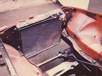
The cooling system follows the line of the standard V8 and uses the V8 radiator which
fits straight onto the later type radiator mountings. The hoses are all standard V8 hoses
and fit without modifications. Two electric cooling fans are used and mount direct to the
transplanted bonnet locking platform as all of the mounting holes are already present. The
fans are operated by a thermostatic switch mounted in the inlet manifold which switches
via a relay mounted in the original donor cars wiring. The heater control valve was the
original unit from the four cylinder car and this was mounted at the back of the V on an
adapter which in turn was mounted at the rear of the inlet manifold. This adapter was long
enough to allow sufficient clearance for the throttle mechanism and fuel piping which fills
most of the available space at the rear of the manifold. Finally the fan belt was a standard
MG V8 one which runs in a slimmed down Rover front pulley (originally a double for the power
steering drive) and water pump pulley. The alternator used is a modern Lucas Type-A 133/55
amp unit which fits the restricted space found in this application. The Lucas ACR types
are too deep and the rear of the alternator fouls the rocker cover. This explains the
use of the Delco alternator of the standard car.
The Fuel Injection and Exhaust Systems
The fuel injection is to my mind the real icing on the cake as far as this conversion is concerned. The system used is the "federal" specification Lucas 'L' type system. This system is very similar to the current Rover Vitesse system although there are many detail differences to suit the different requirements. To give a little history to this system takes us back to the time when BL was planning to introduce the SD1 to the U.S. market. As most of us are aware this market over the recent past has enforced a number of significant changes onto our manufacturers. One of the changes to the SD1 for its U.S. introduction was the requirement to pass certain emission regulations and to maintain the low level of emissions for very many thousands of miles. For various reasons, not least of which was the very accurate fuel metering, the fuel injection route was taken. Midland readers will probably remember seeing in the 70's, Rover SD1's running around on set routes with big signs over the vehicle indicating 50,000 mile emission testing. At that time I was using Rover 3500 SD1's to the UK specification and I had the opportunity to compare a federal car with the UK car. I found the federal car to be very much better in throttle response and acceleration. I was unable to compare higher speeds but I believe that the differences were not very great. The initial responsiveness of the federal car produced a noticeable advantage on the road and I can see why the motoring press at the time kept nudging for a UK specification injected SD1. After all the certification was completed the car was introduced to the U.S. market and was not a success. This had the advantage of releasing production capacity of injection systems and probably led to the introduction of the Vitesse.
The Lucas 'L' type system is similar to the Bosch system and uses a number of
Bosch components. The system works by gathering information from a number of sensors
fitted to a number of engine components. These include the cooling system; the throttle;
the incoming airflow to the throttle; and the distributor. This information is passed
to an electronic control unit (ECU) which acts on it to provide a predetermined
injection of fuel for the correct cylinder at the correct time. The fuel is fed from
a high pressure fuel pump to each of the injectors. The pressure is maintained at a
constant level by a pressure regulating valve which bleeds off excess pressure back
to the fuel tank. The injectors are solenoid valves and the amount of fuel injected
depends on the time the valve is allowed to be open. It can now be seen that the
information passed to the E.C.U. and the programming of the unit can have a profound
effect on the running of the engine. The advantage is that if correctly set up the
engine will provide maximum power for the minimum of fuel. The attached diagram
gives an overall picture of the running of the system. One item which applies to
our system and is not shown on the diagram is the cold start injector. This works
in unison with the auxiliary air valve supplementary on diagram and operates when
the engine temperature is low. The ECU automatically enriching the inlet charge
with extra fuel and air via this cold-start device. This enables the engine to provide
superbly smooth power delivery from the very coldest of starts, which is a well known
feature of fuel injected cars.
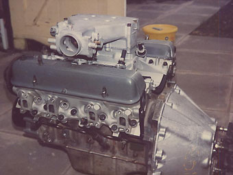
With the basics of the system explained, I move to the choice of the federal
system as opposed to the more powerful Vitesse system. The federal system was chosen
for its compactness. The overall height of the system when fitted to the engine is
less than the Vitesse type. Now this is critical in an MG engine compartment if a
standard bonnet line is to be maintained, which was a particular consideration for
our car. In addition with the flop in the American market there must be quite a few
Federal systems, which are now redundant, lying somewhere. Even if only the Federal
manifold and plenum chamber are available the remaining parts to complete the system
can be raided from a Vitesse. We were fortunate in obtaining a complete system
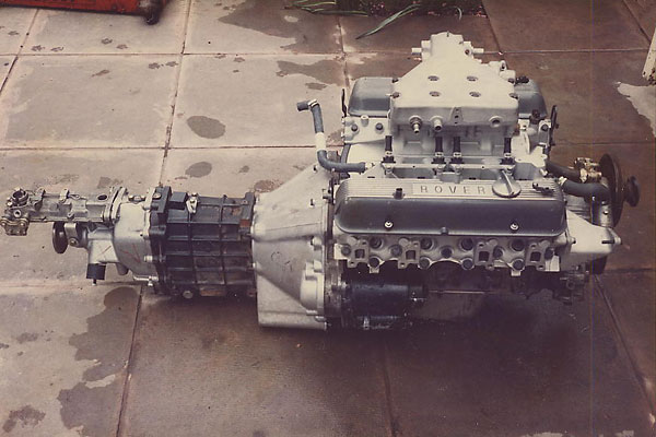
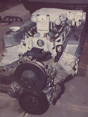
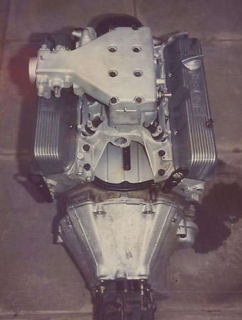
including a wiring harness which makes for much easier connection. The photo's show
some of the components to be used.
To fit this system into an MGB is far from simple and involves very many
secondary modifications to other areas which will be covered in due course. The
first problem to overcome was the bonnet clearance. With the engine bolted in it
was found that the plenum chamber, the squarish shaped top part of the inlet manifold,
fouled on its front edge with the bonnet. The amount of extra clearance required was
very small and was gained by machining down the plenum chamber, on its face which
mates to the inlet manifold, by 1.5". This is about the maximum that can be taken
off before the underside of the throttle body contacts the top of the left hand
rocker cover. It is however, enough to give clearance to the bonnet so that it
doesn't touch at any point. Taking this metal off does reduce the internal volume
of the plenum which could affect the engine response, but in practice the effect
on the engine's running is not noticed. With this now fitted the remaining engine
mounted components were fitted. An area which required modification was the roof of
all the inlet ports which had to be lightly ground to give room for the nose of the
injectors. All other injection components are bolted or secured to the engine with
no other modifications being required. With the reduced height of the plenum chamber
comes the reduction of space between the throttle body area and the top of the left
hand rocker cover. This also reduces the working area for the insertion of the fuel
pipe and wiring. This also means that no's 1, 3, 5 and 7 injectors become virtually
buried and immovable with the plenum chamber in place. This is especially so for
the two middle injectors. What this means is that the injectors wiring and fuel
lines have to be fitted prior to fitting of the plenum chamber. It also means that
in service any work in that area requires the removal of the plenum which is
fortunately an easy operation as long as care is taken to ensure a fully airtight
seal between the inlet manifold and plenum chamber afterwards.
Moving away from items mounted on the manifolding leads us to the air flow
meter. This device does exactly what its title indicates by way of an internal flap
valve. This valve is quite bulky being about the size of an alternator (new types of
meter as found on the '0' series E.F.I. engines of hot wire types and are much
more compact). The size of this valve together with the requirement that it be
mounted 9" from the throttle has meant the assembly is bolted to the nearside inner
wing in the indentation found above the front damper. With this mounted and the
interconnecting hose fitted, it has filled the space between the cylinder head and
inner wing. It has also meant that for the moment there is insufficient clearance
between the cooling system overflow tank and intake side of the valve to accommodate
a filter which would have a sufficiently high airflow rate for this engine.
Resighting of the overflow tank would be desirable, but the mounting of all the
extra control units and relays has left no space large enough for this tank. In
time this will have to be solved to ensure a clean air supply and a remote air
filter will probably be used but the problem of space still remains. Noise levels
from this open intake when the engine is under load are quite muted but it is still
loud enough to leave no doubt of the potency of the engine - certainly much quieter
than an open-carbed MGB.
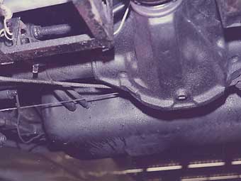
The next item to be tackled was the fuel pipes. As I said earlier this
injection system is a full flow system which in other words returns petrol not
used to the fuel tank. This obviously requires a feed and return pipe for the
fuel. Piping used is standard steel fuel piping. One pipe run follows the line
of the standard pipe from the area of the fuel pump mounting to the heater area
of the engine compartment. This pipe is used to return fuel to the tank. In the
engine compartment braided rubber fuel hose is used to connect the pressure
regulating valve to the return pipe, each joint being securely clamped. At the
rear the return pipe passes over the rear axle before entering the tank through
a fixed pipe in the front face of the tank. Next to this return pipe is the
feed pipe, this is again mounted in the front face of the tank for reasons which
will be covered later when the tank modifications are covered. This feed pipe is
of a very much larger diameter than the return, about twice the size. This large
diameter pipe feeds the inlet side of the high pressure fuel pump and has to be
of such a size in order to be able to flow the very high volume of fuel required
by the system. At this point in the system it has to he remembered that fuel is
at atmospheric pressure and therefore has no extra pressure assisting the flow.
Connection of the tank feed to the fuel pump, which is still mounted in the same
location as the standard pre rubber bumper electric fuel pump, is by reinforced
rubber piping which follows the body line over the rear axle to the inlet of the
pump. The outlet of the pump is of the standard diameter pipe as the fuel has now
been pressurized and sufficient flow is available due to the pressure. The feed is
connected to next section of steel pipe by the same type of reinforced rubber
hosing. The steel fuel feed now follows a totally separate route from that of
the return pipe. It passes through the rear bulkhead just above the floor level
on the offside and near the corner by the transmission tunnel. It then follows
the line of the tunnel and floor joint to a point near the front of the tunnel.
The pipe then rises over the tunnel to the nearside before rising under the
dashboard and forward through the front bulkhead and into the engine compartment
roughly under the nearside bonnet hinge. From there another reinforced hose
connects this pipe with the fuel piping of the injection. I would add that the
internally routed pipe is of one complete run with no connections inside the
cockpit also all other hoses and clips are new and of a type which is designed
to cope with the fuel pressures found in this type of system. This is of course
to ensure safety as well as reliability in operation.
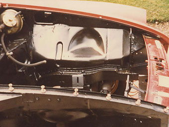
The fuel tank has, as has already been indicated, come in for its own
series of modifications. These are geared to ensure smooth operation of the
injection system. The tank used is a larger than standard 13.5 gallon unit which
is identical to the standard item other than the larger capacity. The standard
sender unit is used but the fuel outlet found on the side of the tank is sealed
as this is redundant. Externally the two extra pipes previously mentioned are
fitted to the front of the tank as described. Where they pass inside the tank
they are brazed to prevent leaks. At this point I think it worthwhile to say
that a brand new tank was being used and one that had not seen any petrol.
(Specialists may weld used fuel tanks, but I wouldn't even heat one with a hair
dryer!) Moving inside the tank finds both pipes running to a 'bowl' in the centre
of the tank floor. This 'bowl' has an access hole for fuel to enter it which can
then be drawn by the pick up pipe. The purpose of this bowl is to provide a
constant fuel supply whilst the vehicle is being cornered when fuel surge occurs.
The hole in the bowl being too small to allow its rapid emptying under these
conditions but being large enough to not restrict fuel supply. With the fuel
return emptying into the same bowl a sufficient fuel reserve is maintained until
the cornering has ceased. These conditions only apply when the fuel level in the
tank was below half, above that level and surge doesn't present this problem. If
the bowl wasn't there and the tank level was to drop then when the car was
cornered the fuel pick up could be uncovered and suck air which would cause a
severe hiccup in the engine. (Sudden loss of engine power whilst cornering could
be most unwelcome). One final point is that the new pipe exit positions where to
our choice and not fixed by any technical restrictions. We chose to have the runs
where they are to suit our mounting of other components. A quite reasonable
alternative would be to have the pipes pass through into the boot area which
would improve fuel pump access and possibly risk of damage or failure to the
pipes or pump. The last item of the fuel system worthy of mentioning is the high
pressure fuel pump. This item has much smaller external dimensions to that of the
SU pump. This and the differing pipe runs allowed us to use the standard pump
bracket to be used in a shrunken form. It also allows more than enough room for
the fitting and operation of the rear anti-roll bar common to all post 1976 MGB's.
Wiring all of these extras together was made easier with our possession
of a wiring harness and the correct connector blocks, even so this area was not
simple until the arrival of the correct wiring diagram which then made the operation
straightforward. All of the extra electrical components connected with the control
of the injection are mounted in the engine compartment with the exception of the
master E.C.U. which is mounted in the passenger footwell. The final mounting
position of these components was decided upon to take into account the following
requirements, ease of fitment, sensitivity to heat or other contaminants, any
other special mounting conditions for that component. In the end we have managed
to mount most items in relatively similar positions to those of the SD1 for which
our system was originally fitted. The extra loom for the injection only required
a few alterations to wiring length. The only area which could have been extensively
modified was in the wiring run to the E.C.U. In the MG body it could have been
shortened but this would have meant shortening no less than 28 wires (the total
number of connections in the whole system exceeds 100 which does show how simplified
the diagram is. The extra length of the loom is lost in the bulkhead area. Related
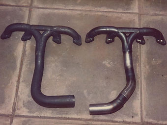
to the inlet side is the exhaust which was tackled in the following way. Tubular
manifolds were obtained and were fitted to the cylinder heads with the use of new
bolts, tab washers, and export type gaskets. The left hand manifold can be easily
fitted but the righthand manifold required a little extra cutting and rewelding
to run it closer to the block for clearance of the steering pinion shaft. Even
with the reshaping done, the manifold could not be fitted until the engine was
raised slightly on the offside. This required the offside engine mounting rubber
to be temporarily loosened. If the manifold was bolted to the head with the mounting
loose we found insufficient room to get in to tighten the mounting nut. The result
is that the mounting has to be loosened and the engine raised, followed by the
slotting into place of the manifold. The engine is then lowered and mounting
tightened followed by the bolting of the manifold to the head. The rearmost top
manifold bolt presents difficulty as it cannot be easily fitted due to the pinion
shaft being so close. Persistence does eventually win but what is explained in a
few lines took several hours of knuckle skinning. The exhaust system is a standard
chrome bumper V8 type including the mountings. The two front down pipes had to be
cut to match the non-standard manifold: but this is a very simple operation. The
only other exhaust modification was to the pipe between the two silencers to obtain
clearance for the non-standard Spax telescopic rear dampers.
Transmission
The engine and its ancillaries now having been covered leads to the next major area for conversion and that is the flywheel, clutch, and gearbox. The gearbox we've used is a Jaguar version of the current Rover five speed box. The differences between the Rover and Jaguar applications as far as the external view is concerned is confined to the bell housing, which is a separate bolt-on item, and the remote gear change. Inside the box there are other differences, none of which have a detrimental effect on the new application. One other small item which is different is the operating rod of the clutch slave cylinder release mechanism. In the Jaguar application it is shorter and will not operate the Rover clutch.
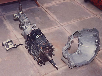
The changes required to allow this box to be fitted to the V8 engine and
subsequently into the MG are simple. First the remote assembly has to be changed
for the Rover SD1 type which is longer (see the photo). This is a simple
unbolt-one-and-bolt-on-the-other. The next job is to obtain and bolt on a Rover
SD1 V8 bell housing along with the clutch operating pushrod from the same car. At
this stage the gearbox could be offered up to the engine and bolted to it. The
logical flywheel and clutch to use is pure SD1 V8 which will present no problems.
In our case however we were in possession of a genuine MG V8 flywheel which of course
bolts straight onto the crankshaft. We were also in possession of a genuine used
MG V8 clutch assembly and a new SD1 assembly. On comparing the two we found that
we could use either as items such as clutch splines and flywheel mountings were
identical. Being as the SD1 item was new, that was used and it was bolted onto
the MG V8 flywheel. (It would appear that in the event of non availability of the
genuine MG V8 component, then the later and much more common SD1 parts can be
substituted.) With the clutch assembled the last part fitted was an SD1 release
bearing before the engine and gearbox were bolted together (see photo). The
slave cylinder used is the SD1 type which is connected to an SD1 flexi hydraulic
pipe. This pipe is a little too long for the MG application and could usefully be
shortened by 2". The other end of this pipe is fixed to the original pipe mounting
which is attached to the body. The union at this end does not match that of the
standard MG clutch metal hydraulic pipe and a special one was made up which uses
the MG top union with the Rover SD1 bottom union. The master cylinder is a standard
MG item with no changes. There are no problems with this clutch arrangement and in
use it provides a light, progressive and powerful clutch.
The actual fitting of the gearbox into the body was thought to be the most
potentially difficult area of the conversion mainly because of the near total lack
of any knowledge on this subject. However, in practice it was quite simple. The
body modifications have already been covered and the only item not covered are
the changes to the removable gearbox crossmember. The two angled supports on the
crossmember have to be carefully removed in order that after modification they
can be refitted. From the cut end they are first shortened by approximately 5/8"
so that when refitted to the crossmember they sit 5/8" lower. At this point the
cut down mountings are offered up to the crossmember and then carefully moved
outwards, each by an equal amount, until the holes which take the gearbox mounting
rubbers studs on each of the mounts, are separated by 6-1/8" centre-to-centre.
This is an increase of about 3/4" compared to the spacing found on the standard
crossmember. When positioned, the mounting can be re-secured by a tack weld.
Prior to offering the crossmember up to the new gearbox the one mounting hole for
the gearbox rubbers is elongated upwards to ease fitment of the gearbox. The
rubber mounting used is the SD1 cotton reel type which fits straight into the
gearbox casing. With the crossmember now modified and the mounting rubbers also
fitted the whole assembly was offered up to the chassis and to our surprise we
found that the existing chassis to crossmember positions still aligned perfectly
and so presented no problem in just bolting up in the normal manner. The last
problem to be sorted with the gearbox was the gear lever as this now sits about
1" towards the rear of the car. This means that when the interior trim and tunnel
console is refitted there is not enough clearance for the lever to freely move
into 2nd and 4th gear positions. Two slight modifications resolve this problem.
Firstly, the hole in the tunnel itself is relieved at the rear slightly and secondly
the gear lever, which has an inbuilt damper which is fairly thick, is slimmed down at
the top of the damper crimping.
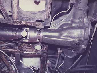
Moving now to the propshaft, which is a one off, as is its method of
attachment to the rear axle. As can be seen from the photo's, the overall length
of the gearbox is a lot shorter than any of the original types of gearboxes. This
meant that none of the original MG propshafts would fit without considerable
lengthening. The actual measurements involved are: (1) standard gearbox to axle
distance = 31", our gearbox to axle distance = 38.5". In other words, ours is 7.5"
longer. To solve this we obtained an ex dynometer driveshaft which had an inbuilt
damper and length of 40". This shaft was built to the same specification as normal
propshafts and to look at is identical to them. This shaft also had the larger
size of flanges which matched the gearbox flange but not the axle flange. To solve
the mismatch at the axle end we have made up a very neat and effective adapter
which has been carefully machined to preserve balance. It neatly has Allen headed
bolts which fit into shouldered holes in the adapter. These bolts then match the
smaller flange found on the axle. This allows the adapter to be bolted securely
onto the axle flange. The adapter is also drilled and tapped on the forward face
to match the larger propshaft flange which allows the propshaft to be bolted straight
onto the adapter. In use we have found this arrangement to work very well with no
hint of imbalance. Now that the propshaft can be bolted to the axle we come to the
problem of the required length of the propshaft. Since the length of the adapter is
1.5" and the overall distance at rest between gearbox and axle is 38.5" we had the
propshaft shortened to 37" with the sliding joint in its halfway position. This work
was done by Hardy Spicer (GKN) at their service department at the rear of the Castle
Bromwich factory. They of coarse did a fine job of work and included was rebalancing
and painting at a very low price. One other minor problem encountered was the
clearance in the tunnel because of the larger diameter tubing of the propshaft.
This required the handbrake pivot to be cut down, rethreaded and use of a thinner
nut to clear.
The rear axle first used was the standard B axle which has the 3.9:1
ratio. This was also a disc wheel axle, which is slightly wider than the wire
wheeled axles. This axle was retained for ease of fitting and on cost grounds.
We were fully aware that the standard ratio was unsuitable for the characteristics
of the V8 engine but we reasoned that 5th gear would equate to direct 4th of the
standard V8 which would be acceptable as an interim measure. This turned out to
be true but another restrictive element was more apparent than predicted. This
was the rev range of the V8 engine. It can be seen that our initial specification
of engine uses mainly standard components and particularly the earlier type of
cylinder heads. In practice we have found that the engine does not breathe too
well above 5000 rpm which doesn't encourage use of that rev band. This also has
the effect of shortening all the gears so that gearchanging becomes more frequent
and time consuming. Even so the acceleration from standstill to orbit was only a
little slower than the NASA Space Shuttle. Another problem found was in the area
of rear wheel/tyre clearance with the outer part of the wheelarch which has become
more apparent with suspension settlement and heavier loads (ie: me and Barry).
Looking at the problem from the underside showed that if a line was drawn vertically
through the wheel in it's centre (when looking from the rear) the whole assembly
could be seen to be too far outset and to centralize the whole assembly would require
the track to be reduced by about 2". This alignment problem is due to the type of
alloy wheel used and as we wanted to retain this type of wheel as we have a spare
set, we started to look at the possibility of using a wire wheel axle which is about
2" narrower as standard.
Our first idea was to obtain an MGC wire wheel axle with a 3.3:1 or 3.08:1 ratio not in abundant supply and even when found the S/H prices weren't that attractive either. The other possibility was to have a wire wheel axle case fitted with the V8 crown wheel and pinion which would again be a costly affair. Our savior came in the form of an advert from Roadstyles, the axle people who had obtained a limited supply of new original V8 crown wheels and pinions with a price of £145. The end result is them fitting one of these V8 CW&P's into a wire wheel casing and charging a figure very considerably less than the cost of either of our earlier considerations. We have had to add a couple of items to the new axle in the form of brackets for the rear anti-roll bar and flexible brake pipe mounting. We have made up these brackets and had them arced onto the casing before it was filled. Also this axle retains the original size of propshaft flange which means the modified prop and adapter fit straight on. (If we had obtained the MGC or standard axle all the flanges would have been the same size and therefore the prop would have had to be lengthened by the 1.5" length of the adapter.) The axle uses standard wire wheel type half shafts with the original disc wheel hubs and brakes. Fitted, the new axle solves the wheel problems but renders the speedo inaccurate. This will be solved with the fitting of a V8 speedo. At the time of writing the axle is in the process of being fitted so road impressions aren't yet available. However, we anticipate that with the lengthening of all the gears, which will suite the engine characteristics, and the immense torque will insignificantly reduce the acceleration and if they do then plans for another 40 to 50 bhp are already afoot.
Brakes and Suspension
This is a most important section and has received as much priority as any of
the more glamorous sections. The modifications carried out are basically simple but
effective. The suspension has uprated bushes in the joints. The springs are standard
rate V8 type. Dampers are uprated levers at the front whilst at the rear a Spax
telescopic conversion kit was used. As previously indicated, a post '76 standard rear
anti-roll bar was fitted along with a standard type front bar. Wheels are alloy and
are of a design very similar to the standard V8. I believe that early Costello cars
possibly had this type of wheel. Tyres are 185/70 Dunlops at the moment but now the
rear arch clearance problems are sorted the possibility of some lower profile tyres
is being considered. Overall we have aimed for a suspension set up which retains a
standard ride height so that the car can clear raised man hole covers and the tops
of ramps in the common multi-story car parks. We hare also aimed for a compliant
suspension which is why we haven't up-rated the springs. To control the suspension
movement well is desirable which is why the dampers are up-rated. With this set-up
the car handles well with the rear axle being apparently very well controlled, bearing
in mind the power transmitted. The specification is by no means the last word. Advice
from knowledgeable circles has been well received and will in time be put into practice.
The brakes are to the same specification as the standard V8. This means the
front discs are the fatter items with the pads operated by hybrid calipers which have
been assembled from instructions given by Peter Laidler. Briefly, the standard B caliper
is too narrow in the bridge area to cope with the thicker V8 disc so it has to be
replaced with a caliper that is wide enough in that area. The V8 caliper is the obvious
solution but the cost is sky high. However looking at other calipers made by Lockheed
(Automotive Products) provides a cheaper solution by using part of the caliper fitted
to the Triumph 2000/2500 range and part of the MG caliper. To do the job safely requires
a number of other new seals, bolts, etc and it is a modification which shouldn't be
considered unless all the extra little items are being used. A small point of interest
is that we are running without dust shields to aid the flow of cooling air around
the disc. If the dust shields were retained then either MB ones would have to be fitted
or the originals would have to be modified. Brake lining material is standard at the
moment alithough different materials might be used to try and reduce the excessive
amount of brake dust produced, which covers the front wheels very quickly. As far as
the efficiency of the brakes are concerned they are well up to the performance apart
from a very slight tendency for the rear wheels to lock up earlier than the front on
less than ideal surfaces. A solution to this is already in hand as it's undesirable
when road surfaces are less than perfect.
Miscellaneous Modifications
In this section are listed the few remaining small items which required modification.
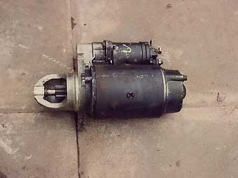
The starter motor is a mixture of Rover end plate and MGB motor and solenoid. This is
effectively the same as the standard V8 MG starter.
The alternator is a Lucas item of the new generation flat-back type. This particular
one is a 133/55 which is the same as can be found under the bonnets of the MG Maestro
and it produces a maximum of 55 amps. This type of alternator has to be used to give
clearance to the rear, otherwise the alternator fouls out on the offside rocker cover.
The alternator is also mounted on a bracket salvaged from an early Rover 3500 P6B
(2000 shape) This type of bracket has the alternator sitting on top of it. The drive
belt used is a standard V8 item. The ignition system used as mentioned is the SD1
constant energy type. Apart from the distributor, there is an ignition pack which
has the special coil on its back The distributor is connected to the ignition pack
by way of a 'shielded' lead. To avoid the need to alter this lead, the ignition pack
is mounted in approximately the same position as the coil on the earlier MGB, which
is on the offside inner wing. The heater control valve is the same as found on the
4-cylinder cars, but to match it to the totally different inlet manifolding has
required the making of another adapter. This is a simple affair involving making of
two simple brackets out of 1/4" plate. One matches the inlet manifold outlet whilst
the other matches the valve. The two plates are then brazed to a length of pipe
which in our case is routed past the throttle linkage. The final position of the valve
was determined by the pipe and control cable rune to it. Next the original MG wiring
loom is not compatible with the twin electric cooling fan control as fitted to V8's.
The circuit required the fitting of a relay to overcome the problem. The tachometer
(rev counter) was adapted to accept the V8 impulses and since modification it has
proved accurate. Finally the speedo cable was specially made with one end to suit
the gearbox and the other to suit the speedo head. The overall length is similar to
the cable found on overdrive MGB's and whilst we were at it we had a spare cable made.
A suitable cable is probable made for another car but we had the opportunity to have
these made immediately so the offer was accepted.
General
At this point we now have over 3 months of daily use with the car and during
this time there have been very few problems to sort out. In fact we have suffered from
less problems than a lot of people find with new production-line oars. To summarize them
will take only a few lines. The first problem was one which we caused ourselves and this
was the rear main oil seal of the engine. On this early engine the seal is a rope one and
has to be soaked in oil prior to fitting. Obviously we didn't soak it long enough as it
didn't seal. This meant that we had to lift out the engine to replace the seal. The
replacement was certainly soaked long enough before fitting as we don't want to make a
habit of changing them. At the moment the new seal is working as it should.
The only other minor problem has been with fine tuning. Originally a Federal
control box was used for the injection This was replaced by a Vitesse control box
which did seem to cure the slightly lumpy tickover that was the problem. Unfortunately,
the fuel consumption dived to 15 mpg so the Federal box was replaced and the fuel
consumption rose to 20.4 which it has been maintained. Further fine tuning on a rolling
road with the aid of an accurate gas analyzer is planned which should eliminate this
very minor problem. I should add that when on the move there are absolutely no problems
at all.
As far as road impressions are concerned, all I can give is opinion. To try and
be as objective as possible I will compare our car with cars that I have recent and
extended experience with. One point to note is that all the road impressions so far
are with the lower rear axle ratio. The acceleration is markedly better than a Rover
Vitesse and the ease at which cars such as Golf GTi's are left for dead reinforces the
impression of high performance. Mid-range response is better than any car I have
experienced with the possible exception of Jaguar V12. Top speed is totally academic,
at the moment, as max revs in 5th could easily be attained. I'm looking forward to the
car with the Y8 axle ratio, which should only enhance the vehicle's character. Lastly,
a number of other people who have experience of the MGB GT V8 have sampled the car and
all have been mightily impressed, which is most rewarding.
The total cost of this project so far is in excess of £3000, but the resulting
package does make it a cheap high performance car. Whether another car could be built
on such a budget would depend largely on parts availability, especially with regard to
the Federal type of manifolding. I would think that somewhere there is a stock of these
Federal systems after all they were fitted to the Federal SD1's and TR8's. It's time
for someone to unearth a stock of these in some dark corner of a forgotten warehouse.
To conclude, I will restate that this is an amateur project and what I have
written should not be taken as a bible of how it should be done. It is simply a
record of how WE have done it to result in a vehicle which fulfilled all of the
goals set by its builders. It is not the final specification as refinements and
other changes will be carried out as an on going project and whatever the results
of our labors are then I will attempt to pass them on for the benefit of others.
Whilst thinking of others I would like to mention several people for their part in
this project so far: Firstly my good friend and colleague Gordon Upton whose skill
with the welding torch greatly assisted in the more visible areas of bodywork.
John Hill and Jon Miller of John Hills Ltd. who have been more than helpful with
the supply of a large number of parts at more that favourable prices and conditions,
and Sue, whose patience has been stretched beyond all reasonable limits yet the
coffee still flowed.
Updates
1. Barry Yardley's MGB V8 Swop
Original engine suffered from piston breakages in the land area (between rings). The cure was
the re-bore and fitting of normal oversize pistons still at 1O.5:1 compression ratio.
Original MGB V8, Range Rover pre SD1 small valve cylinder heads have been replaced with standard
SD1 items. The worth of this change is very substantial and is worth about the same in increased power
throughout the whole rev range as the next mod for which the makers claim 22hp on a standard SD1. The
other mod is the substitution of the SD1 camshaft with a Piper Magnum 270. As a matter of interest,
this cam has a reduced duration down from 285 degrees to 272 degrees. However, in contrast the lift
is substantially increased from 0.39" to 0.44". Ignition and injection settings have not had to be
altered.
Current peak power is now in the region of 200 plus horsepower. Torque has been substantially
increased to a peak which must be between 220-230 ft lbs. As an indication of the tractability
of the engine, it will pull on full throttle in 5th gear from tickover speeds. With this sort
of torque/power, traction becomes a problem even from tickover speeds. Wheel spin can be produced
even in 3rd gear.
Fuel consumption is fairly steady at 21 mpg with the vast majority of the mileage being
covered in bouts of 10 miles or less.
2. Roger Parker's MGB V8 Swop
At time of writting I am well advanced in the conversion of my old roadster to fuel injected
V8. The engine spec is identical to Barry's, so should also be a 200 bhp machine. Differences
so far encountered when compared with Barry's conversion are now listed.
a) Engine bay conversion is to pre rubber bumper V8 spec (ie: top mounted oil cooler).
b) The steering rack is a genuine V8 which had a broken casing. A 4-cylinder casing was
used to replace and is a straight swop (both items being pre rubber bumper).
c) The steering column is the original pre-70 solid pre collapsible type. It has been
shortened by some 3+" with the excess being cut off from the lower end before being re-splined.
The splines are the same whether the old bulky U-loint is used or whether the later rubber
bumper U-joint is used. The later type is more compact.
d) The original outer column is used after being shortened by 3+" (less shortening
than the actual column) The early lower column mounting is also used but is now mounted
closer to the bulkhead to allow for the shorter length. These steering mods allow the
original dashboard and larger type intrements to be used which keeps the period look.
e) The engine mounting as fitted to the chassis are from the V8 conversions so as the
V8, later rubber bumper type are shown N.L.A. These are used in conjunction with standard
MG V8 rubbers and engine block brackets. Engine height is the same as for a standard set
up.
f) The gear box cross member has been modified as for Barry's hit as the whole
engine/gearbox is some 1" further back than Barry's. The mountings have been moved rearward
that amount in addition to the listed mods.
g) The gear stick hole has had to be cut back further to allow engagement of 2nd and
4th gears. For cars with post-'71 centre consoles, a shortened gearbox remote assembly
or a modified and cranked gear lever would be required to allow retention of the console,
h) Propshaft used is a one off 37" shaft with Rover sized joints and flanges.
i) My original 1968 front cross member has been retained with no sump clearance
problems. However the rack mountings required very slight modifications to lower the
angle of the pinion shaft to suit its longer length and to give clearance for the
exhaust manifold.
j) A couple of engine differences are worthy of mention. First, I have used an SD1
front cover which has the longer capacity (deeper rotors give 20% more flow) oil pump.
This also has the advantage of being compactable with the later electronic distributors.
Another advantage is that the front oil seal is a lip type compared with the earlier
rope seals. Incidentally, the MG V8 water pump is a direct fit. Front pulley fits and
this is the cast MGB V8 c. early Rover V8 saloon type. SD1 and Range Rover types are
different. Finally, as my block is an early one it has a rope type rear crank seal.
The rear main bearing housing has been machined to take the later or MG type of much
more efficient lip seal.
All remaining modifications and components will be as for Barry's car. My conversion
has reached a stage when the main engine/box is being fitted along with manifolding,
cooling system, and oil system.
Suspension will be as follows: roadster front springs, V8 bushes, uprated dampers,
3/4" roll bar, rear MGC springs, Spax shock absorbers.
Brakes will be to V8 spec.
A full list of parts used can be compiled reasonably easily if you desire.