
Troubleshooting Guide for Rover 14CUX EFI
The British V8 Newsletter, Volume XV Issue 1compiled by: Curtis Jacobson
INTRODUCTION
The 14CUX Electronic Fuel Injection system provides a reliable and efficient microprocessor controlled fuel management system. The function of the system is to precisely supply an appropriate amount of fuel into the inlet manifold to suit prevailing engine operating conditions.how is it difference from the earlier Rover systems (14CU)?
how is it different from other OEM systems?
MegaSquirt
R.A.M. Auto Repair, Inc.
110A N. White Horse Pike
Lindenwold, NJ 08021
856 - 435 - 2200
"Import and Domestic Repair Facility - Routine Maintenance to Major Repairs"
1990 Range Rover (3.9L) VIN SALHV124XLA405140
The system was used from 1989 - 199X on engines with displacements of 3.5, 3.9, 4.2 and 4.6L and on Discovery, Range Rover, Range Rover Classic, and LSE (verify) plus MG RV8. (Morgan? TVR?)
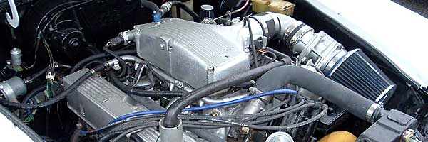
BASIC MECHANICAL PARTS
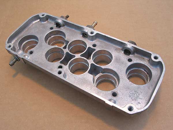
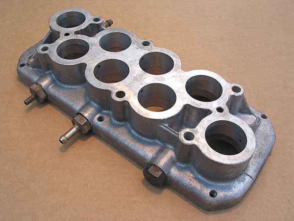
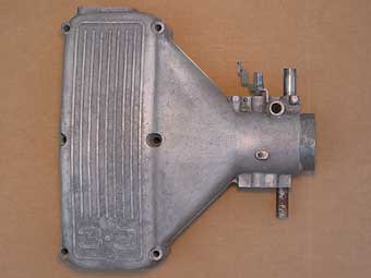
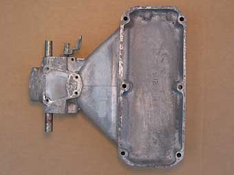
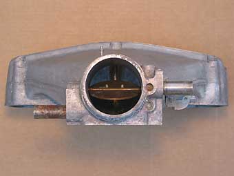
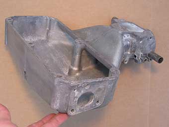
Note: the Rover 14CUX fuel injection system is relatively "tall" compared to alternative induction systems, so its mechanical components typically must be modified before it can be installed on sports cars. The lower plenum chamber is typically milled down by approximately 0.8", and sometimes the steel trumpets and upper plenum chamber (i.e. the "plenum cover") are also cut down.
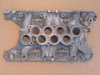
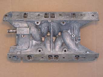
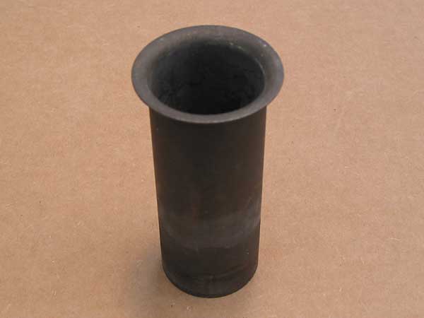
Before any of these operations are undertaken, it's prudent to remove the trumpets from the lower plenum chamber. This is easily accomplished if you know the trick: heat the parts in an oven! The aluminum will expand more than the steel trumpets, and you'll be able to simply pull the trumpets out by hand. Obviously, you should first degrease the parts, and also you should wear oven hot mitts. From personal experience I can advise that the trumpets come out easily if the parts are hot - but also that they cool quickly! - Several cycles of going in-and-out of a 400 degree oven will be required. If you get a particularly stubborn trumpet you can gently cool it by wetting a thin strip of cloth in water and lowering it into the tube. The cloth doesn't have to actually contact the steel trumpet to have a dramatic and rapid cooling effect. Be very careful because the steam produced could easily burn you.

The lengths and diameters of runners in the intake system, and also the volume of air in the plenum from which they draw air will affect the performance characteristics of the overall system. Although we lack the resources to comprehensively and scientifically evaluate the performance effects of modifying these components, we can make a few physical measurements and see how they fit "rules of thumbs" published by others. The inside diameter of each trumpet is 3.81cm. The cross-sections of the runners in the cylinder heads are significantly smaller, but in the intake manifold the runners quickly transition up to round cross-sections of about 3.8cm diameter each. The average total length of all eight runners measured from intake valve to open plenum is about 38.75cm. (Runners 1 and 8 are approximately 41cm long. Runners 2 and 7 are approximately 39cm long. Runners 3 thru 6 are approximately 37.5cm long.) Based on these measurements, and on articles written by engine guru David Vizard describing the behavior of Helmholtz Resonance induction systems, we can calculate that the Rover induction tract seems to be tuned to achieve peak torque at approximately 5130rpm. Furthermore, according to David Vizard's explanation and formulas, if the runner length is shortened the induction tract's tuning will be shifted to achieve peak torque at an even higher engine speed. (If the runners average 37.95cm, the modified system will be tuned to provide peak torque at about 5310rpm.)
(Volume of air in the plenum?)
(The butterfly is 65mm in diameter. The inside diameter of the hose from the throttle-body is 73mm. The inside diameter of the hose into the mass air sensor is 80mm.)
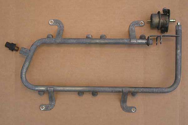
The Fuel Rail provides fuel to all eight injectors. For the fuel injectors to operate properly, a fairly constant fuel pressure is required, so a Fuel Pressure Regulator is mounted on the fuel rail at the rear of the plenum chamber. The regulator is a mechanical device controlled by plenum chamber vacuum; it ensures that fuel rail pressure is maintained at a constant pressure difference of 2.5 bar above that of the manifold. When pressure exceeds the regulator setting excess fuel is returned to the fuel tank.
To check the fuel pressure, a gauge is fitted to the supply line immediately after the fuel filter. The ignition is powered up, and the gauge is read. The pressure reading should be between 34.0-38.0psi (2.390-2.672 kgf/cm^2). Next, turn the ignition switch off and observe the pressure drop in the system. After one minute, pressure should drop no more than 10psi (0.7 kgf/cm^2). To check for a leaking injector, first check the spark plugs! (A leaking injector will typically result in a sooted-up spark plug.) Range Rover advises that all eight injectors can be removed from the manifold without being disconnected from the fuel rail (which is presumably still full of fuel.) If you can manage to get them out and inspect them for leakage, you should observe no more than two drops of fuel per minute from any injector.
The Fuel Pressure Regulator on our example system is marked "W. Germany", "Lucas", "2.5", "8RV", "84924A", and "7.21311.02".
THE CONTROL SYSTEM
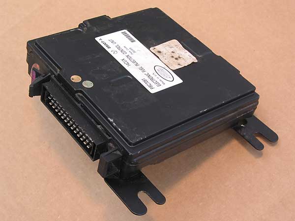
The Electronic Control Unit is the "brains" of the fuel injection system. The ECU is located under the front right hand seat. Various sensors are fitted to the engine to measure and to communicate operating parameters to the ECU. The ECU uses this data to quickly and constantly adjust the amount of fuel delivered. The ECU does this by modulating pulses of the electrical current that opens the fuel injectors. The fuel injectors are divided into two banks of four, and the ECU only has two "outputs" (i.e. one for each bank of injectors.) Inside the ECU, a microprocessor and other components are mounted on printed circuit boards. The ECU is connected to the main harness by a 40 pin connector. The connector terminal/cavities on the ECU housing are not labeled.
The ECU on our example system has a sticker with the following markings: "PRC7081", "14CUX", "85007A", "Electronic Fuel Injection Control Unit", "Made in U.K.", "Date Code 3689", "Land Rover" (plus a bar-code).
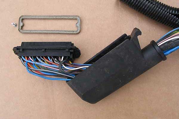
The EFI Cable Harness Assembly is connected to the ECU by one 40-pin Amphenol connector (part number 143-70011). The connector is sealed, but can be disassembled by removing two hidden screws from the ECU-side (they're hidden under a rubber seal.) Cable pin positions are labeled on the side of the connector that is hidden by the plastic cover. Consult the photo above to see how the pins are numbered (because it's not as simple as it should be!) The pin positions correlate to cable insulation color codes as follows:
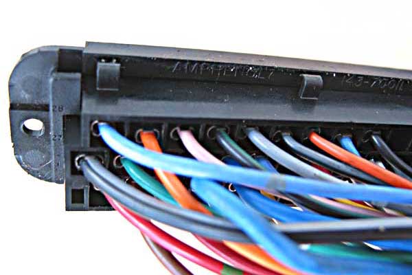
| "Bottom Row" - pins 1 to 13 (they're numbered from left to right as shown in the photo) | ||
| 1 | Red/Green | Idle bypass valve - circuit 1 |
| 2 | Brown/Orange | Return from the fuel injectors - see also 11 and 13 |
| 3 | Yellow | Throttle position sensor - see also 20 and 25 |
| 4 | Black | Power to the oxygen sensors and to the relay that powers their heater coils |
| 5 | Grey/Black | Tune resistor |
| 6 | Yellow | Road speed input |
| 7 | Green/Blue | One side of coolant temperature sensor - see also 25 |
| 8 | Purple/Yellow | Windshield defroster input, if fitted |
| 9 | White/Light Green | |
| 10 | Black/Yellow | |
| 11 | Yellow/White | Right bank of injectors - cylinders 2, 4, 6 and 8 |
| 12 | Blue/Red | To "main relay" |
| 13 | Yellow/Blue | Left bank of injectors - cylinders 1, 3, 5 and 7 |
| "Middle Row" - pins 14 to 27 (they're numbered from right to left as shown in the photo) | ||
| 14 | Black | |
| 15 | Brown | "Battery" supply |
| 16 | Blue/Purple | "Fuel pump relay" |
| 17 | Grey/Yellow | "Purge valve" |
| 18 | White/Pink | |
| 19 | White/Grey | "Ignition" supply |
| 20 | Red | Throttle position sensor - see also 3 and 25 |
| 21 | Yellow/Black | Air conditioning thermostat input, if fitted |
| 22 | Blue/Red | |
| 23 | Blue | Signal from the LH oxygen sensor |
| 24 | Blue | Signal from the RH oxygen sensor |
| 25 | Red/Black | One side of coolant, fuel, airflow & throttle-position sensors - see also 3, 7, 32 and 35 |
| 26 | Green/White | Idle bypass valve - circuit 1 |
| 27 | Black/Grey | Tune resistor |
| "Top Row" - pins 28 to 40 (they're numbered from left to right as shown in the photo) | ||
| 28 | Blue/Grey | Idle bypass valve - circuit 2 |
| 29 | Orange | Idle bypass valve - circuit 2 |
| 30 | (Not Used) | |
| 31 | Black/Green | |
| 32 | Grey/White | One side of fuel temperature sensor - see also 25 |
| 33 | Black/Grey | Air conditioning compressor clutch relay, if fitted |
| 34 | Orange/Black | Transmission gear switch signal |
| 35 | Blue/Green | Air flow sensor - see also 25 |
| 36 | Black/Green | Air conditioning condenser fan output, if fitted |
| 37 | (Not Used) | |
| 38 | (Not Used) | |
| 39 | White/Black | "Engine speed signal" cable and 6.8k ohm resistor |
| 40 | Black | |
1. Where two colors are given, the first is the basic color and the second is a "stripe" or "tracer" color.
2. Pins 4, 23, 24, 30, and 31 were also NOT USED on vehicles that weren't equipped with catalytic converters.
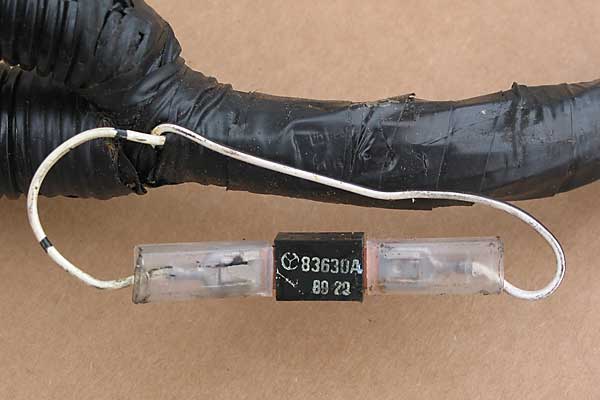
A "tune resistor" was included in the wire harness so that one ECU part number could serve multiple vehicle markets. (Multiple computer programs are stored within the ECU, and the ECU "decides" which one to use, based on what resistance it senses on the tune resistor circuit.) The tune resistor is located about one foot down the harness from the ECU connector.
You can visually inspect the wires attached to the tune resistor, and based on the cable insulation color you may differentiate between the following: - White wire, 3900 Ohms, USA and European vehicles with catalytic converters. - Green wire, 470 Ohms, UK and European vehicles without catalytic converters. - Yellow wire, 910 Ohms, Saudi vehicles (without catalytic converters.) - Red wire, 180 Ohms, Australia and "the rest of the world." (Note: all four types of Rover tune resistors are rated for 0.5 Watts.)
The Tune Resistor is connected to terminal positions 5 and 27 on the ECU connector. If you wish to check the resistor, first disconnect power to the system, second disconnect the EFI Cable Harness Assembly from the ECU, and finally simply measure resistance (using an Ohmmeter) from pin 5 to pin 27. (Resistance isn't polarity dependent.)
The Tune Resistor in our example system is marked "83630A" and "8920". The cable to it is color coded white, but it also has a black tracer.
Preliminary test procedures: 1) verify that the correct tune resistor is fitted, and that resistance across the resistor is correct to spec. 2) with ignition switch "off", verify that the battery supply (pin 15) is receiving at least 10VDC. 3) with ignition switch "on", verify that the ignition supply (pin 19) is receiving at least 10VDC.
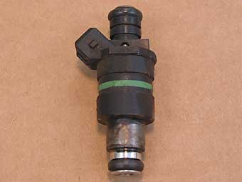
Fuel injectors are the precision valves that meter fuel delivery. The eight fuel injectors are fitted between the pressurized fuel rail and the inlet manifold. Each injector comprises a solenoid operated needle valve with a movable plunger rigidly attached to the nozzle valve. When the solenoid is energized the plunger is attracted off its seat and allows pressurized fuel into the intake manifold.
Minimum fuel flow per injector is 160-175cc per minute using alcohol (for testing), or 180-195cc per minute using gasoline, when tested at 36.25psi (2.54kgf/cm^2) at 20C +/- 2C.
Wiring faults on the injector circuits (and within the injectors) can be tested for at the ECU connector. Turn the ignition off and disconnect the ECU connector. Check the right bank of injectors by measuring resistance between terminals 2 and 11. Check the left bank of injectors by measuring resistance between terminals 2 and 13. In both cases, an Ohmmeter reading of 4-4.5 Ohms is expected. If the reading is 5-6 Ohms, suspect one bad fuel injector. A reading of 8-9 Ohms could indicate two bad injectors, and a reading of 16-17 Ohms could indicate three bad injectors. In any case, if the overall circuit resistance isn't 4-4.5 Ohms, proceed to checking for wiring faults or for open-circuit injectors.
The Injectors in our example system is marked with a green stripe painted around their circumference.
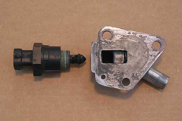
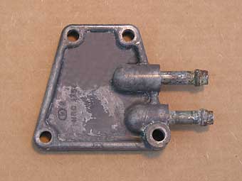
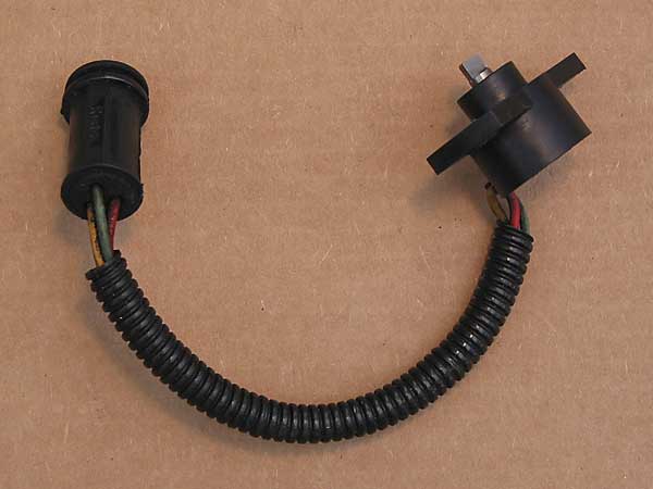
The purpose of the Bypass Air Valve is to provide a mechanism by which the fuel injection system can alter the amount of air delivered to the engine, especially when the engine is at idle. The "Bypass Air Valve" is actually a solenoid motor with a plunger that acts as a valve in conjunction with an aluminum casting that it mounts into. The valve-body casting is mounted on the rear surface of the plenum chamber by three bolts. The valve is connected by a rubber hose to the intake tract ahead of the throttle butterfly. The valve includes an integral stepper motor, featuring two windings that are controlled by the ECU, so the ECU can control the valve aperture. For example, the valve provides extra air to maintain idle speed when the engine is under increased mechanical load such as when the air conditioning compressor is engaged.
The Bypass Air Valve has four terminals, but on our example valve they aren't marked on the valve housing. To identify them, refer to the mating connector. You may verify continuity in the windings by measuring across terminal pair cavity-A (orange wire) and cavity-B (blue/grey wire), and then by measuring across terminal pair cavity-C (green/white wire) and cavity-D (red/green wire); in both tests Ohmmeter readings should show 40 to 60 Ohms resistance. (If you prefer, you may take these measurements from the ECU connector by measuring at terminal pair 1 and 26 or terminal pair 28 and 29.
Reportedly, the Bypass Air Valve is one of the weakest links of the Rover 14CUX system. It can stick, and we're told that the most typical symptom of this is a fast idle of about 1,500rpm, and also "searching" idle speed when descending hills. WD40 can sometimes un-stick the valve temporarily. The Bypass Air Valve on our example system is marked "73312A" and "82494". The first marking is certainly a part number, and I suspect that the second marking is a date code that indicates the valve has been replaced at some point. If you're familiar with automotive wiring, you'll probably recognize that the connector and terminals for this valve are Packard Weather-Pack components. (Packard Electrical Division was part of GM, and was spun off to become Delphi.) The valve itself bears a striking resemblance to AC Delco part number 25527077, which was used on all 4.3L GM V6 engines and most 5.7L GM V8 engines. If you need one of these valves, purchasing the General Motors spec part from your local parts counter will be considerably more economical than dealing with Range Rover.
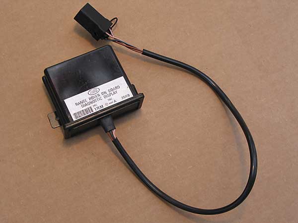
The fuel injection fault display provides fault codes readouts in a way that's very easy to read and interpret. The display has a sealed molded plastic case that is actually made from dark red transparent plastic. Light emitting diodes can be seen though the side of the case when a fault code is displayed.
The Fuel Injection Fault Display on our example system is marked "Land Rover", "Range Rover On Board Diagnostic Display", "PRC", "7067", "17EM", "85008A", and "3589". It has a 4-lead pigtail on it that's about 18" long, and the 5-pin connector on the end of the pigtail is unmarked except for terminal cavity numbered 1 thru 5 (connected as follows: 1 - brown/orange, 2 - "black/grey", 3 - "pink", 4 - not used, and 5 - "brown/white".)
SENSORS
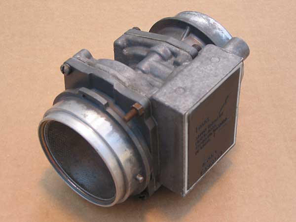
The air flow sensor consists of a cast aluminum body through which air flows. A proportion of this air flow is ducted off from the main air stream to the side into an aperture in which two wire elements are situated: one is a sensing wire and the other is a compensating wire. An integral electronic module controls a measured current of electricity through the sensing wire to produce a heating effect. The compensating wire is also connected to the module but is not heated. Engine intake air passes over the two wires causing a cooling effect, and as they're cooled their electrical resistance slightly changes. The electronic module monitors the change in resistance (and current) through the wires, and by comparing them is able to provide an output signal that is proportional to the air "mass flow rate."
The Air Flow Sensor on our example system is marked "Lucas", "3AM air flow meter", "Made in Japan", "Service No. 73242A", "Mfg Date 2389", "AFH55-1" and "Hitachi". It has a 6-pin connector on it, with terminal positions labeled "12", "9", "8", "7", "6", and "36" (from left to right).
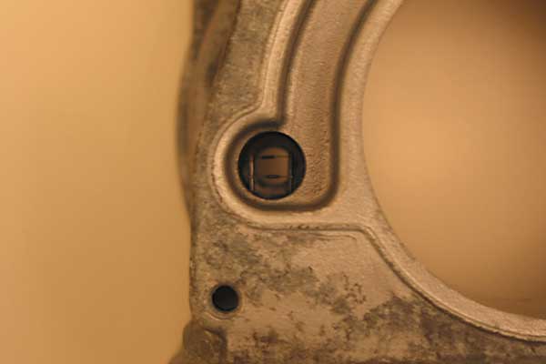
The Throttle Position Sensor is mounted on the side of the plenum chamber inlet neck and is directly coupled to the throttle valve shaft. The potentiometer is a resistive device supplied with a voltage from the ECU. Movement of the throttle pedal causes the throttle valve to open, thus rotating the wiper arm within the potentiometer which in turn varies the resistance in proportion to the valve position. The ECU lengthens the injector open time when it detects a change in output voltage (rising) from the potentiometer. In addition, the ECU will weaken the mixture when it detects the potentiometer output voltage is decreasing under deceleration and will shorten the length of time the injectors are open. When the throttle is fully open, the ECU will detect the corresponding throttle potentiometer voltage and will apply full load enrichment. This is a fixed percentage and is independent of temperature. Full load enrichment is also achieved by adjusting the length of the injector open time. When the throttle is closed, overrun fuel cut off or idle speed control may be facilitated dependant on other inputs to the ECU. The throttle position sensor is designed to be self adaptive, which means that (at least in theory) adjustment is neither possible nor necessary.
To troubleshoot the Throttle Position Sensor, first disconnect system power and then disconnect the EFI Cable Harness from the ECU. Using an Ohmmeter, verify that resistance between terminals 3 and 25 is between 4000 and 6000 Ohms. Next, reconnect the EFI Cable Harness to the ECU, and turn the ignition key switch "on". Take Voltmeter readings from pin 20 to ground. With the sensor in the throttle-closed position, you should read 0.085 to 0.545 Volts. With the sensor in the throttle-open position, you should read 4.2 to 4.9 Volts. In between these extremes, turning the throttle position sensor should produce a smooth sweep of Voltage readings.
The Throttle Position Sensor on our example system is marked "215SA", "84925A", "Lucas", "Made in UK", and "2499". It has a 3-lead pigtail on it that's about 6" long, and the 3-pin connector on the end of the pigtail is marked "Rists". The three cables to the pigtail are color coded "yellow", "red" and "green" respectively.
Road Speed Transducer (photo not available)
The Road Speed Transducer is mounted on a bracket on the left hand chassis side member adjacent to the motor mount. The transducer provides road speed data to the ECU. The ECU in turn detects vehicle movement from the road speed input and ensures that idle speed control mode is disengaged. If the speed transducer fails, the ECU idle speed control will become erratic. The transducer also provides road speed data to the electric speedometer, the use of which deletes the need for the upper speedometer cable.
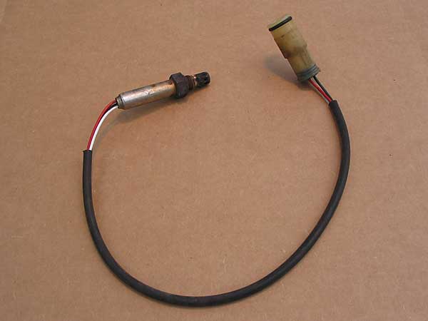
The Oxygen Sensors provide a feedback loop: based on their signal, the ECU is able to estimate the air/fuel ratio of combustion. The sensors are located on the exhaust pipes just downstream of the exhaust manifolds. Because oxygen sensors are more accurate when they're warm, the oxygen sensors are equipped with integral heater elements. The heating elements shouldn't be necessary once the engine reaches operating temperature.
The Oxygen Sensors should provide a fluctuating output between 0.50V and 1.00V. (Measure Voltage at the ECU while the vehicle is running, by connecting your meter between terminal 4 (high) and terminals 23 and 24, respectively. An unexpectedly low voltage reading may indicate an air leak, a contaminated injector, or low fuel pressure. An unexpectedly high voltage may indicate too high fuel pressure, a leaking injector or injectors, or a saturated carbon canister.)
The Oxygen Sensors on our example system are marked "Lucas", "3LS", and "NTK D3G". They have 3-lead pigtails that are 17" long, and the 3-pin connector on the end of the pigtail is unmarked. The three leads are color coded "red", "white", and "black" respectively.
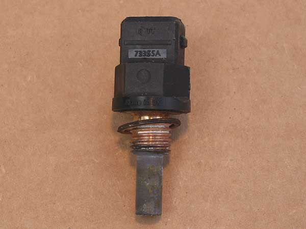
The Engine Coolant Temperature Sensor is threaded into a boss on the intake manifold. Note: this sensor contacts the coolant fluid, and thus its threads need to be sealed appropriately. When the engine is "cold", as determined by this sensor, the ECU richens the fuel mixture by lengthening the time injectors stay open. The ECU reduces the length of fuel pulses as the engine reaches normal operating temperature.
| Ohmmeter readings should relate to temperature as follows | |
| 10C (14F) | 9100-9300 Ohms |
| 0C (32F) | 5700-5900 Ohms |
| 20C (68F) | 2400-2600 Ohms |
| 40C (104F) | 1100-1300 Ohms |
| 60C (140F) | 500-700 Ohms |
| 80C (176F) | 300-400 Ohms |
| 100C (212F) | 150-200 Ohms |
The Engine Coolant Temperature Sensor on our example system is marked "73355A", "Lucas", and "Made in UK". It has a 2-pin integral sealed connector.
Fuel Temperature Sensor (aka: "thermistor" or "thermally sensitive resistor") (see fuel rail photo above)
The Fuel Temperature Sensor is threaded into a boss on the fuel rail, forward of the plenum. Note: this sensor does NOT contact fuel, and thus it can be removed without gasoline leakage. The information provided by this sensor is mainly of interest when the engine is being started. If the fuel in the fuel rail is already hot, the ECU knows a "hot" engine is being re-started, and can adjust the mixture accordingly.
The Fuel Temperature Sensor on our example system is marked "Lucas", "Made in UK", and "73273D". It has two terminals.
Disclaimer: This page was researched and compiled by Curtis Jacobson. Views expressed are those of the author, and are provided without warrantee or guarantee. Apply at your own risk.
Photos by Curtis Jacobson (except the first one, which was by Greg Myer). All rights reserved.