
TR6 Powered by a Chevy 350 V8 and Widened 11 Inches!
 |
 |
| Picture 1 | Picture 2 |
|
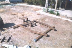
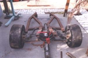
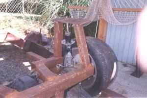
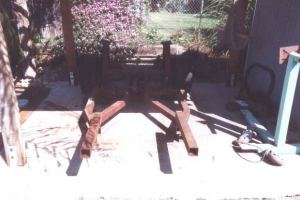
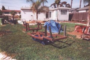
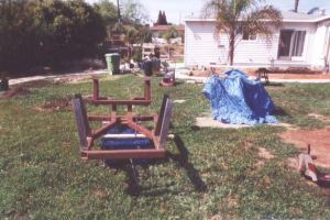
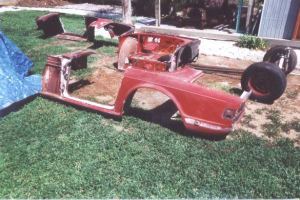
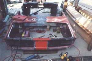
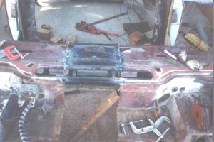
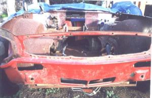
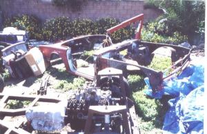
(as recorded by Dan Masters) Wayne wrote: Well, first off, I took a welding class 18 years ago, 2 semesters of an auto body class 1 year ago, and I liked my TR-6 but thought it lacked power. Besides that, any time you heard a strange noise you would wonder what part you were going to have to order. A Chevy 350 and commonly available parts would change all that. My V8 TR-6 started with 3X3 0.090"-wall square tubing. I looked at an original frame and set it up similar to that. First I started with an 84 Dodge Conquest TSI Turbo IRS. It is a 3.49 Posi with disk brakes. I welded up the outer frame rails and the rear end brace pictures 1&2. | |
 |
 |
| Picture 3 | Picture 4 |
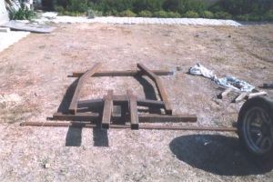
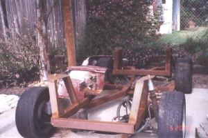
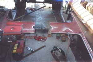
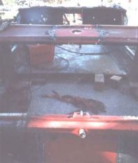
| Next I added the inner frame rails, picture 3, and this gave me
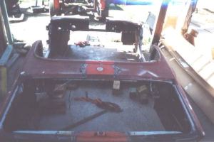
the basic platform for the IRS. This brings us to pictures 4&5 and mistakes 1&2.
I went to bolt in the rear end and found the rear bracing was too narrow to accommodate
the pumpkin, so it was angled out far enough to fit the pumpkin and the Dodge rear carrier.
| |
 |
 |
| Picture 5 | Picture 6 |
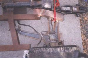
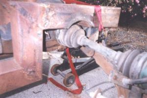
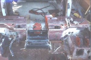
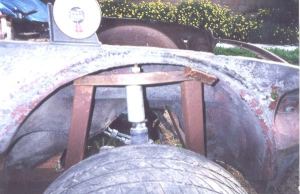
| Mistake 2 was, now that the pumpkin sat where it should the CV joints also hit the
rear brace, so it was gusseted with 1/4" pipe, pictures 6&7.
| |
 |
 |
| Picture 7 | Picture 8 |
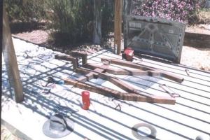
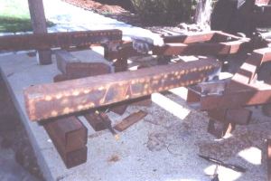
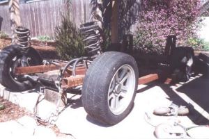
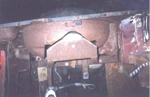
| Pictures 8&9 show the rear strut towers and rear frame rails welded in place.
The towers are 2X3 0.120"-wall with a 1/4" plate cap.
| |
 |
 |
| Picture 9 | Picture 10 |
|
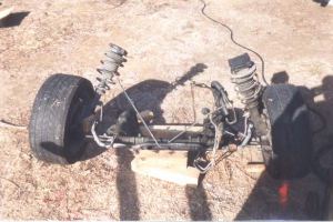
The front end is from an 86 Mazda RX-7 turbo, with aluminum lower arms,
power rack and pinion steering, with 4 piston disks. The unit comes out complete
by removing about 8 bolts. By getting the front end from a turbo car it gave
me the same bolt pattern as the rear, 5 on 4 1/2" Ford pattern. The only
bad thing was that, to use the Conquest wheels, spacers had to be run. When you
use spacers the studs are too short. You can't buy 1" longer studs in that
thread, so they are now 1/2" after drilling and pressing. This could be construed
as mistake #3. In order to keep the frame level, I added a 2X3 0.120"-wall shim
and 3X3 0.120"-wall front frame rails. These of coarse were boxed and fishplated.
| |
 |
 |
| Picture 11 | Picture 12 |
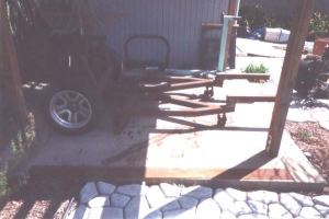
| If anything was going to need extra support, this section was it. (Pictures 11, 12, &13.) | |
 |
 |
| Picture 13 | Picture 14 |
| Pictures 14&15 show the front end set in place without strut towers. | |
 |
 |
| Picture 15 | Picture 16 |
 |
 |
| Picture 17 | Picture 18 |
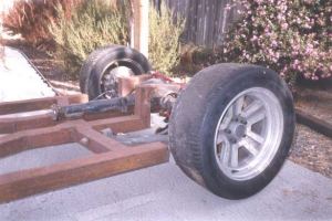
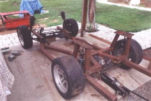
| The next 3 pictures (16, 17, &18) show the 2X3 0.120"-wall
towers in place but not capped (because camber and caster haven't been measured yet.)
Although it may not look it in the pictures, everything has been measured
level and cross-measured to about 1/8". I want to go down the road straight!
Fortunately someone in the Triumph club has an RX-7 (the same club that
is displeased at me for cutting up a '69 TR-6), and I was able to get the
angles, ride height, and strut-cap height measurements. I welded on the front
1/4" strut top plates. I also cut some pipe to the correct length to go between the
strut bodies and the strut caps to mimic the ride height and give me a rolling
chassis (picture 19). That is it for now on the chassis with more to come
later but now - the body...
| |
 |
 |
| Picture 19 | Picture B1 |
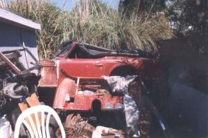
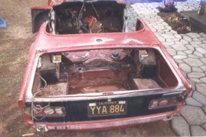
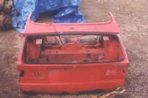
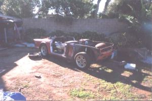
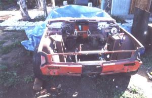
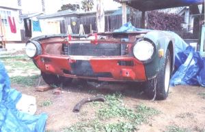
| Picture B1 is how I got it. It was complete except for the front
fenders and the hood. The front nose was already removed by drilling out about a dozen spot
welds and cutting the top of the front fender supports, about 5".
| |
 |
 |
| Picture B2 | Picture B3 |
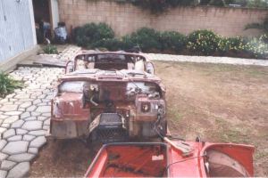
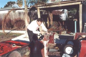
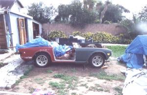
| Pictures B2 & B3 show the '69 TR-6 getting ready to be
gutted for a chop job. With hack saw, Sawsall, and jig saw in hand I started chopping
the car in half, yes lengthwise see picture B4. I cut it 1/2" to the side of center
in the front to retain one of the windshield mounting nuts. It was cut down to about
1" from the tranny tunnel. From there I went around the tunnel approximately 1"
from the edge.
When I got to the floor, I cut from there to about 1" inside of the rear inner fender well. Next I cut down the center of the rear of the car all the way thru the roll pan. The trunk floor was cut out leaving the body mounts in the trunk section just cut out. I wish I had left these mounts in the body section, it would have been easier to mount the body later but it's to late now. | |
 |
 |
| Picture B4 | Picture B5 |
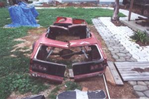
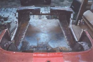
| Lastly I cut the top section above the gas tank and the inner fender wells. I left
the top section in so long because it helped to hold the thing together, but
I didn't want to bend it by leaving it to last. The results are shown in pictures
B5 & B6.
| |
 |
 |
| Picture B6 | Picture B7 |
| When I got the car, I actually got a car and a half and this
half made it a lot easier to section the car back together (picture B7). This piece
was hit on the passenger side in the rear and was buckled in the corner but it was
just what I needed. To section it together again I started with the floor pan.
I didn't want to buy a Triumph floor and cut it up so I got heavy guage sheetmetal
instead.
Everywhere there was a body contour in the floor I cut both sides of the contour about 3/4" inches. Next the sheetmetal was cut to the floor opening size + 1 1/2". The sheetmetal was woven above the low spots in the floor and below the high spots. Before welding I checked for being straight. It was measured side to side in multiple spots and cross measured. I had a friend helping because you can't do this by yourself. Measure, measure, measure and then weld (picture B8). | |
 |
 |
| Picture B8 | Picture B9 |
| It is tough cutting apart something you welded wrong or backwards. Before you
do the sectioning you need a flanging tool. I didn't have one so I made one
from a cheep pair of Channelocks. The jaws were ground flat and parallel
to each other with a 1/32" offset. These are used to overlap the sheetmetal
you weld together. It makes a joint weld stronger than just a butt weld.
The rear sectioning was a little tricky. The car was going to be 11 1/2"
wider so I needed a section 12" but the rib for the trunk gasket had to be
left long, as this rib moves towards the latch about 1/2". To get a consistent
rib, it was cut long by about 8" on each side. A couple of inches extra on each
side of the section and a couple of inches on the body are removed. This is all
needed to blend the body lines back together (see pictures B9 and B10).
| |
 |
 |
| Picture B10 | Picture B11 |
| Next piece to section is above the gas tank. I decided to cut my section with
half circles in it to cover the old gas cap hole rather than sectioning in
a bigger piece. This piece is going to be too long. The trunk edge is straight
but the convertible top edge is curved. I cut my section piece 1/2" passed
the curved piece and flanged it enough to fit in correctly (picture B11).
| |
 |
 |
| Picture B12 | Picture B13 |
| This next picture (B12), is with both the gas tank sections
welded in. The front sectioning piece was cut 1/2" off center because when I cut
the car it was 1/2" off for a windshield retaining nut. If you did the rear section and
the last one, this one is a walk in the park. I flanged most all of this
piece except the hood rain gutter (picture B13).
| |
 |
 |
| Picture B14 | Picture B15 |
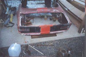
| Picture B14 is the front section welded-in except for the area
around the old ashtray opening. This will be taken care of when I do the dashboard.
Remember I said measure, measure, measure and then weld? Well I must have been
asleep as picture B15 will attest to. I have about 1/16" drop on the left weld on
the gas tank section. I will have to cut all the vertical welds, bend it
up, and reweld.
| |
 | |
| Picture B16 | |
|
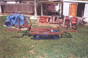
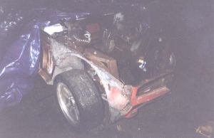
My last picture of this installment (B16) shows the mock-up before I welded
the body. The nose section is sitting on my newly made frame about 1 1/2"
high, but you kind of get the effect. For those with inquiring minds, you
will see part of another TR-6 sticking out of the shed on the left. The rockers,
floor and firewall were shot along with cracks in the door pillars so I have
started to make that into a tow-behind trailer...but that's another story.
By the way, all the cuts were mitered with a borrowed chop saw and my own Sawsall after I borrowed the chop saw for too long. As far as the welder goes, I borrowed that too. My neighbor liked the extra space in his garage so much, that he sold the welder to me. I don't have a garage either, so all this has been done on a concrete slab which is supposed to be our sun deck. | |
SECOND INSTALLMENT(Editor's note: Sadly, we've lost Waynes comments for the second installment...) | |
 |
 |
| Picture B17 | Picture B18 |
 |
 |
| Picture B19 | Picture B20 x |
 |
 |
| Picture B21 | Picture B22 |
 |
 |
| Picture B23 | Picture B24 |
 |
 |
| Picture B25 | Picture B26 |
 |
 |
| Picture B27 | Picture B28 |
 |
 |
| Picture B29 | Picture B30 |
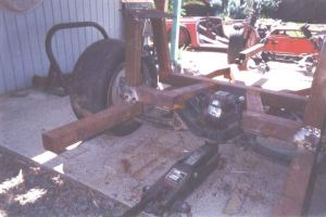
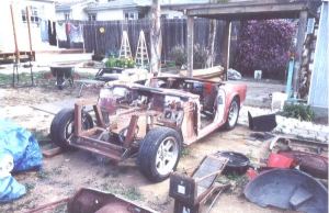
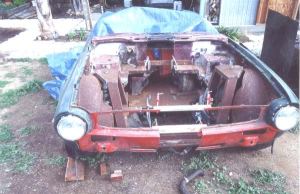
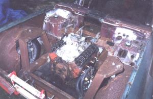
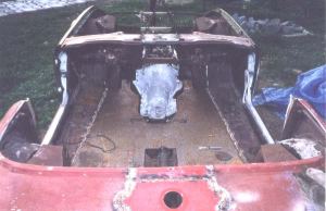
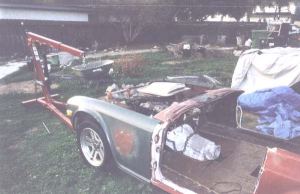
THIRD INSTALLMENTWayne wrote:Pictures F20 - F24 show the frame coming back to me from the powder coater with the suspension and engine installation. The engine is a small-block 400, not a 350. The first 350 I bought was a 327, and the second 350 I traded for was this 400. I guess this makes it a "TR6.6"! Well, the next pictures will be after it hits the street. (Webmaster's note: Terribly and inexplicably, we managed to lose four of the five photos...) | |
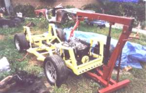 | |
| Picture F24 | |