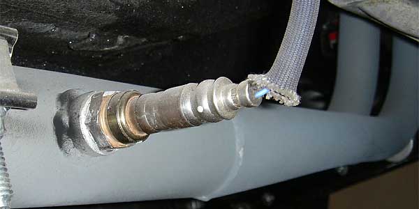
Typical installation of an oxygen sensor for an aftermarket air/fuel meter.
Ignition Tuning 201
How To Use an Air/Fuel Meter to Optimize Your Ignition Timing Curve
as published in British V8 Newsletter, Volume XV Issue 1, April 2007by: Jeff Schlemmer, proprietor of Advanced Distributors, LLC
When it comes to selecting an ignition system, most people are left with more questions than answers. The main goal of improving any ignition system is to get your car to burn fuel as effectively as possible and thus create the most power your cylinders can provide. But how do you test that?
Air/Fuel Monitors are a great place to start! Onboard air/fuel meters can be installed in less than a day by virtually anyone, with little damage to your pocketbook. One example is the Edelbrock unit pictured below in a custom MGB application.
Retail prices for Air/Fuel Monitors range from $130 up to $1500. At the upper end of this spectrum, you're looking for a wideband O2 setup that can be used in conjunction with a chassis dynomometer. When trying to make a decision on what to purchase, be aware that the oxygen sensors that come with the kit can be heated or unheated. A heated oxygen sensor will display data much faster than an unheated sensor and will provide more accurate feedback. A heated sensor can be quickly identified by three (or sometimes four) wires feeding into its connector. Early kits came with single-wire sensors, but I believe these kits have become obsolete.
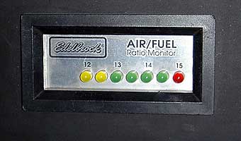
The gauges used in these kits can be found in varying degrees of accuracy and scale. The inexpensive gauges will get you in the ballpark with readings to the nearest 0.5 AFR (air/fuel ratio), typically in a range of 12:1 up to 15:1. For base tuning this is great, but for more advanced tuning a wideband sensor and gauge will be required. Wideband kits, such as the LM-1 portable digital meter, are certainly more expensive but they offer the advantaged of 0.1 AFR accuracy in a range from 10:1 up to 20:1 while taking 12 samples per second.
Installation varies from brand to brand, but they all have a few things in common. They all use a similar oxygen sensor that needs to be mounted in the exhaust system. It is recommended that you install the sensor as close to the engine as possible, but after the collector where the branches of the manifold join. In the case of tubular headers, this would be near the coupling flange or clamp in the header collector itself. In the case of dual exhaust, whichever side offers more room will be suitable.
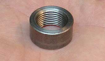
A small steel bung needs to be welded into the pipe. Its typically a 14mm non-plated ring, made to be welded over a three-quarter inch hole drilled into the exhaust. If you don't have access to a welder, most exhaust shops will be happy to perform this task at a minimal cost.
After the sensor is installed, you can run the remainder of the wiring. Be sure to route and secure the wires away from the hot exhaust or your system will be short lived! Most on-board O2 meters simply have two wires to connect. There will be one ground wire, attached to the engine or transmission if possible, and an ignition-fed power source (such as the "green circuit" on most British cars). A test light will help you verify power is only applied when the ignition switch is turned on.
The gauge can be mounted temporarily or permanently.
Before engine tuning, make sure you've filled-up with the same quality and octane of gasoline that you plan to continue using.
Now that you have everything installed, go ahead and start your engine. Allow the engine to warm up to normal operating temperatures and verify that the meter works. Take a few minutes to make sure your engine is idling smoothly at a comfortably low rpm. In most cases this will be anywhere from 600-850 rpm. You may want to verify or set your ignition timing to achieve a smooth, steady idle.
The following information that you will be tuning for will ONLY be at WOT (wide open throttle) so find a safe place to drive where you can keep an eye on the gauge or find a driver to help you out while you watch the meter and take notes. You are looking for an air/fuel ratio of 12.5-13:1 at WOT. You can replace carburetor jets and needles until you are somewhere in that general ballpark. You may see your fuel mixture go slightly leaner as RPM rises - that's excellent!
Make a few runs from 1500-2000 RPM in second or third gear up to 4000 RPM or so. Take close notes regarding your air/fuel ratio (AFR). Note if there are any inconsistencies in each run. You should have very consistent AFR readings unless the driving conditions have changed markedly. Repeat each run on the same stretch of road if you can!
Now you can start making changes to your ignition timing! A change in the correct direction will show on the gauge as a LEANER mixture, with no engine pinging. (Pinging? See below.) Adjust the mixture if needed to get back in the 12.5-13:1 AFR range at WOT. Repeat the process until you find the best timing settings at 2000, 2500, 3000, 3500, & 4000 RPM.
How can you be certain that you've found the best timing settings? The fuel mixture will have gone as lean as you can get it without any pinging present under load. If your gauge readings go rich after making timing adjustments, you've gone in the wrong direction, and your engine isn't burning fuel efficiently.
Take notice of any changes in timing that seem out of place (like a necessary reduction of 2 degrees timing at 2500 & 3000 RPM.) This will create a "map" of the timing your engine prefers. Add-in the initial timing setting you came up with earlier, and you've defined an optimized ignition curve for your application!
Now you just need a good distributor guy to implement your custom ignition curve. (How is this done? Go back and review the ignition article from our last newsletter issue: Ignition Tuning 101: Mechanical Ignition Advance Curves.)
If you can manage to change your timing enough to go leaner than 13:1 at WOT, make the necessary fuel and tuning changes between runs. Disregard any off-throttle or part-throttle information for now.
While a stoichiometric rate of 14.7:1 is great for fuel mileage, it is too lean for high load conditions such as wide-open throttle. Once you get the basics down, we can move on to tuning for fuel mileage or cruise-tuning later. After all, it's all about WOT anyway, right? But those are more advanced topics for a follow-up article.
Keep in mind that all this tuning must be done on an otherwise properly running engine. It is assumed that a basic tune-up has already been performed and all the ignition components are in good working order. This process is to enhance a good running engine, not troubleshoot a drivability issue, although the A/F meter can potentially be used for that too.
Drive fast and take chances!
What is pinging? The characteristic "pinging" (or "pinking") sound is best described as "rattling like a can of marbles" within your engine, not to be confused with the light tapping noises of solid lifters. It's pretty distinct, even if you've never heard it before! When you hear that sound, fuel is burning prematurely and explosively within the combustion chambers. That's called "detonation", and it can be highly destructive.
In some engines, pinging may be heard when too much timing advance is present in a high-load condition (such as driving up a steep hill at WOT). Pinging is aggravated by poor quality or too low-octane fuel. If you get a tank of bad fuel after setting up your timing, driving in a moderate manner or adding a bottle of octane booster to your fuel are good options. Most likely though, this problem will never affect you if you've used an Air/Fuel Meter to optimize your timing curve. If you go too far in advancing your timing, you'll actually see the mixture start to go rich again. As detonation occurs, the fuel charge usually doesn't fully combust, and that shows up on the Air/Fuel Meter. Your base timing setting can always be altered later too, and that will advance or retard the timing throughout the RPM range as needed.
Disclaimer: This page was researched and written by Jeff Schlemmer. Views expressed are those of the author, and are provided without warrantee or guarantee. Apply at your own risk.
Photos by Jeff Schlemmer. All rights reserved.
Support Our Sponsors: (click for info)