 �
�
�
�
Rover P6 Design Innovations
��
as published in British V8 Newsletter, Volume XV Issue 3, December 2007�
�
by: Bill Wardlow of The Motorway Ltd.�
�
When the Rover 3500S debuted in North America, I was already working on P6 models. �
I had a job in a Rover / Land Rover dealership in northern New Jersey. In fact, �
I was driving a beautiful '67 2000TC which I'd bought for $600.00 with a blown �
2nd gear. As I recall, $60.00 worth of parts put me on the road in a car which �
otherwise would have been financially out of the question for me. So you see, I �
came to appreciate the P6 design before there was a V8 in the picture. Its other �
design features, many with an eye toward safety, have left a more permanent mark �
on me than has the aluminum powerplant. I shall touch only lightly on them here. �
A book could be written. �
� Although the photos shown here are of later V8 ("3500S") version of the P6 platform, � almost all of the features shown and discussed were available to the car buying public � from 1964 in the smaller-engined "2000" series models. � �
�
�
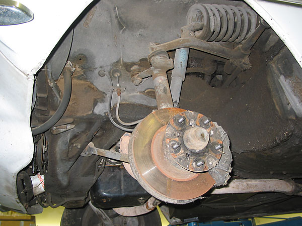
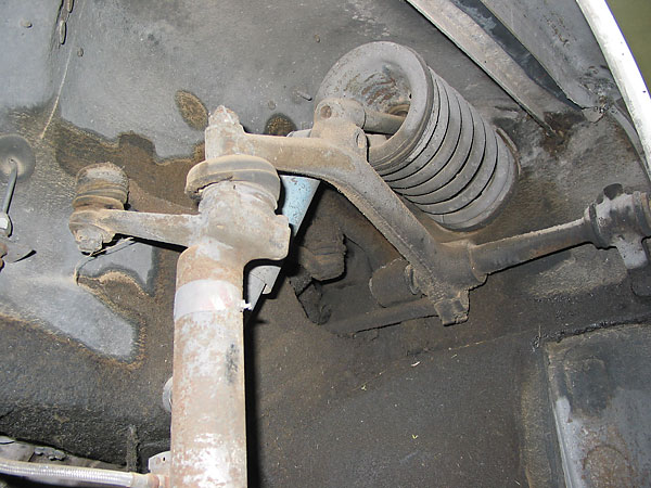
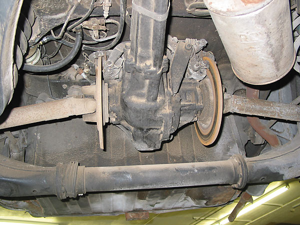
Left front suspension... and in the background: the extremely-robust front crossmember.�
� Notice how the "rocker" transfers verticle wheel motion into fore and aft spring travel. � Also note how the shock absorber actually extends on bump instead of compressing. (This � is favorable in terms of shock absorber longevity.) If you look at the horizontal axis of the � rocker in its bushings, and look below the inner one, you'll see the mount for the � anti-roll bar. The bar itself is a straight hexagonal piece which you can see disappearing � into the engine bay.�
��
�
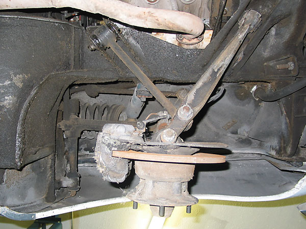
Forged suspension links instead of formed sheetmetal. For its day, the 3-piston brake caliper was massive.
�
�
Another interesting feature is that the brake pads had integral electrical wear sensors,
�
starting with 1969 model year cars. The wiring appears here as a "second brake line".
�
�
Strong stuff! Big, serviceable ball joints.�
�
Why did the car have such an unusual front suspension design? One reason that's �
often reported is Rover had maximized engine compartment packaging space in anticipation �
that one day they might install their turbine engines. Whether there's any merit to �
this suggestion is immaterial - the unusual front suspension provided tangible technical �
benefits of its own. The most important benefit was superior crashworthiness; it kept �
frontal impact force from causing cabin intrusion at a time when frontal impacts usually �
shoved steering columns like a spear toward the driver. �
�
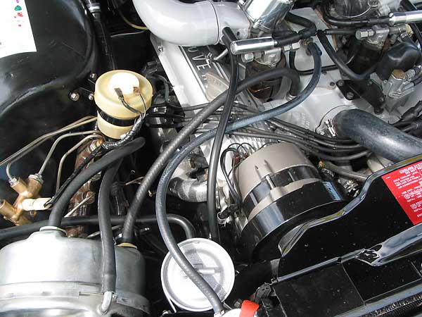
The P6 steering box is located just barely forward of the firewall, with the track rod �
running behind the engine to a bell-crank relay, and thus forward to the steering arms �
on the "swivel pillars". To comply with the federal "Safety Act of 1966", other automobile �
manufacturers were obliged to install collapsible steering columns. Rover was exempt �
from this mandate because their design already provided the same benefit.�
�
The P6 was also one of the first automobile platforms with its engine mounts designed �
to direct the engine and gearbox downward, underneath the vehicle, upon impact. This �
may seem elementary now, but if you recall seeing wrecks of 50's and early 60's cars, �
you may remember seeing engines sitting in front seats.�
�
�
�
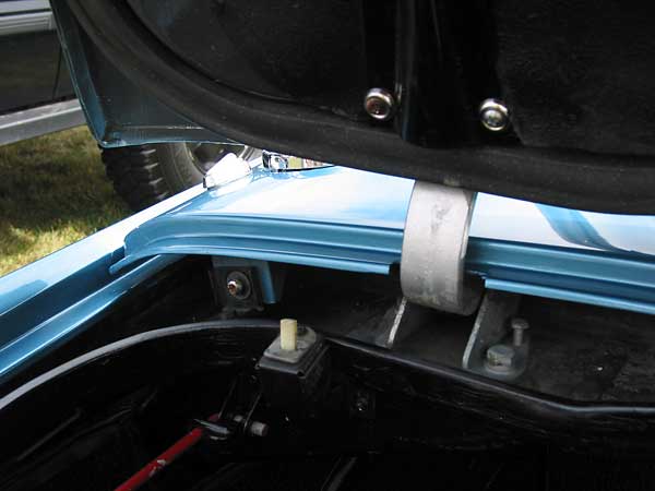
Lance LaCerte's excellent restored Rover 3500S�
is fully documented in its own article. �
� The whole P6 platform, in fact, is one strong unit! It's more rigid under torsional � loading than virtually any production sedan before it. The "base unit" of the P6 was � constructed as one solidly-welded monocoque structure with integral roll cage. It is � possible to remove every body panel from one of these cars, including even the roof � sheet metal, and still have an operating car with a complete cabin structure!�
��
�
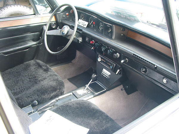
Ergonomically designed interior.�
� When these cars first came out, they had fixed length (separately adjustable) lap and � shoulder belts. Once you were in and belted-up there was no moving around. It was not � a problem because every instrument and control needed for driving was within easy reach. � The controls were laid out logically and intuitively. We could use some of that in � today's cars! I really enjoyed the security of those belts. (They were very like a race car.)�
��
�
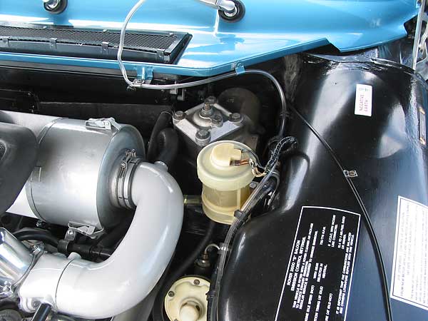
Four wheel disc brakes with booster. The system was well tuned and provided excellent modulation.
�
There are many cars in production today that don't measure up in terms of brake balance and feel.
�
�
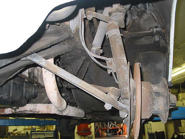
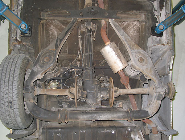
Modified DeDion rear suspension. (Front of car is toward top of the picture.)�
�
Although articles have been written over the years about the P6's unique "modified �
DeDion type" rear suspension, Many of the descriptions of it have been incomplete or �
just plain wrong. To launch into a complete discussion of its features and properties �
here would be beyond the scope of this article. Suffice it to say that the P6 suspension �
is unusually compliant, very steady, and that road-holding on irregular surfaces �
remains among the best I've driven. A brief overview of system components will provide �
a little insight.�
�
The main "DeDion tube" is the straight section across the bottom of the photo.�
�
The "elbow" to the right is rigidly attached to that tube and also houses one wheel hub.�
�
The elbow to the left is bolted to the opposite wheel hub and also to a smaller diameter �
straight tube which rides on bronze bushings inside the larger tube. It therefore is free �
to both plunge and swivel. The axes of the two tubes always remain colinear, so the �
two wheel hubs remain nominally parallel.�
�
Enjoying this article? Our magazine is funded through the generous support of readers like you!
�
To contribute to our operating budget, please click here and follow the instructions.
�
(Suggested contribution is twenty bucks per year. Feel free to give more!)�
� (Note: the fuel tank is mounted above the differential, behind the rear seats, which is the � safest place for it! If the car is rear-ended, there's a generously-sized crush zone between � the rear bumper and fuel.) �
��
�
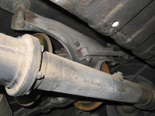
The DeDion tube has an oil filler plug for lubricating the bronze bushings. Note also that the
�
differential housing is on rubber mounts, with a torque rod to restrict side-to-side motion.
�
�
The lower & upper arms shown here function as a "Watts linkage" to locate the hub fore and aft.
�
�
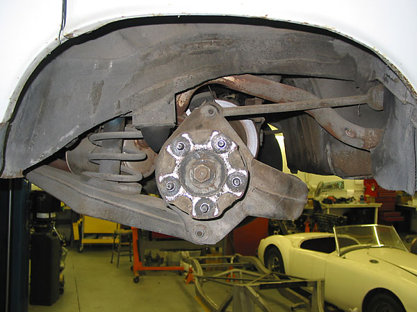
Inboard-mounted rear disc brakes.�
� The inboard brake calipers are hydraulic, but they also include a cable-operated lever� mechanism to engage the emergency brake. This was a very modern feature for its day, and � an important one too. This was a true emergency brake, with enough grip to stop the car � from speed. (It wasn't just a parking brake! Many of today's cars use a small, seperate � brake drum inside the bell of the rotor, or a small secondary brake caliper. These � designs typically provide less braking capability to the hand-brake lever.) �
��
�
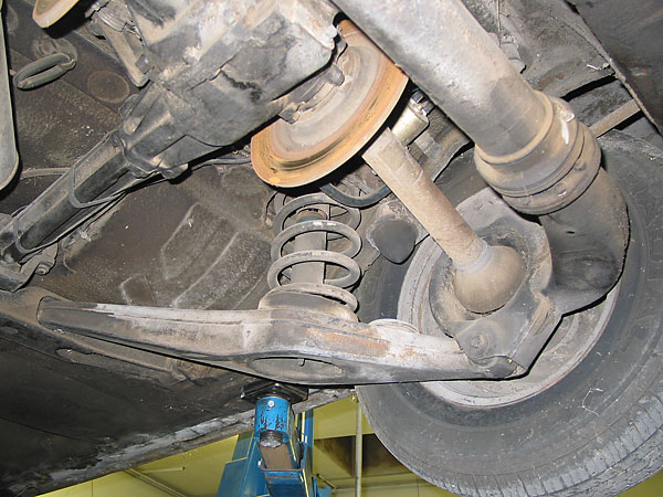
Springs with concentric shock absorbers. �
� The Rover P6 suspension used fixed-length half shafts. Underneath the rubber boots that � are visible in this photo, you would find conventional U-joints. I discovered early on � that all six of the U-joints in the system are interchangeable with Chevy 1/2 ton pick-up � truck parts.�
�Conclusion
��
To think that all of the innovations in the Rover P6 were available over forty years ago�
staggers me, and I was there! These cars were very expensive to build - Just look at �
the welded, ground, and polished stainless steel door glass frames! - and North American �
customer weren't provided very good support by the "factory". However these are stout, �
reliable and safe cars that can still be used as fine daily drivers or as enthusiast �
machines. All they need is understanding.�
�
I've been surprised and a little dismayed over the years to see how many of the aluminum �
V8 engines of the Rover "3500S" P6-variant have been removed and transplanted to other �
vehicles. I think an awful lot of folks are unaware of what a gem of a car came wrapped �
around that motor in the first place. With a little updating and some imaginative �
engineering, I think a 3500S could easily be developed which would give some fairly �
new "Bimmers" a good run!�
�
�
This article is part of a set of SIX! If you enjoyed this article, check out:
�
Rover 3500S Press Release (circa 1969)
�
1970 Rover 3500S Specifications and Pricing
�
Leyland "Eight GE" Concept Car Press Release (circa 1968)
�
Rover V8 History (courtesy of Autocar magazine)
�
Lance LaCerte's Restored 1970 Rover 3500S�
�
Photos by Curtis Jacobson. All rights reserved.�