 �
�
 �
�
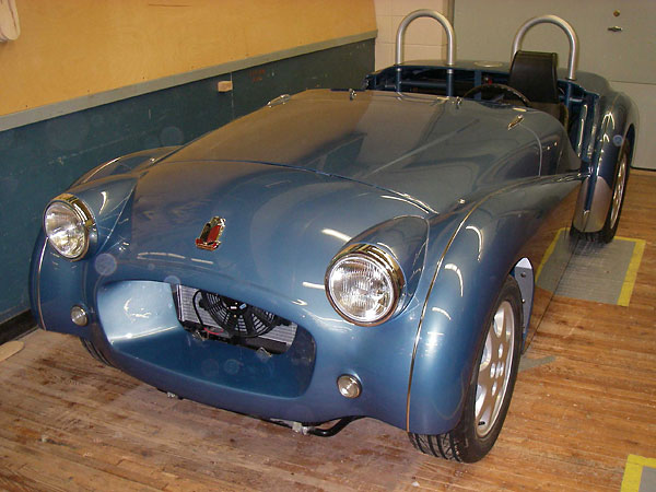
Randy Schultz's Triumph TR3 "Plus 4" Project, Part 1
��
as published in British V8 Magazine, Volume XVI Issue 1, May 2008�
�
by: Randall Schultz�
�
The inspiration to undertake this conversion came from a simple idea: �
"Use the Triumph parts I like, don't use the Triumph parts I don't like, �
and use parts from other cars to produce the ultimate TR3." For me, the �
classic early TR3 body was the strongest styling statement Triumph ever �
made. It defined the spirit of British sport motoring. The TR6 chassis �
represents Triumph's highest development of the body-on-frame concept, �
featuring independent rear suspension as well as rack and pinion steering. �
My intention was to produce a vehicle that captured the essence of the �
TR3, except with better handling, brakes, and engine. I also wanted modern �
reliability and the ability to get service parts anywhere. From my point �
of view, none of the Triumph engines or electrical systems would be �
suitable for the project. �
�
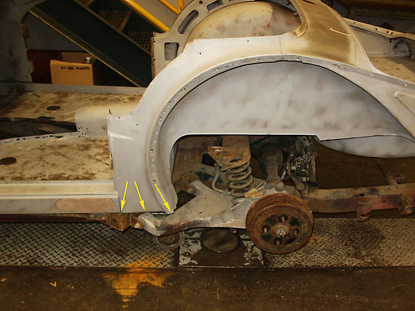
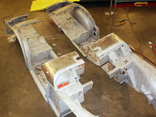
A TR3 body doesn't fit on a TR6 chassis. The TR3 body is narrowest just �
behind its doors - just where the TR6 chassis is its widest! (This �
corresponds to the outboard side of the rear trailing arms of the TR6 �
independent rear suspension.) Even with careful cutting and re-definition �
of the back end of the inner sill boxes, the body still needs to be at �
least four inches wider to fit the TR6 chassis.�

�
�
 �
�
 �
�
�
I took my lead from famous auto designer Alec Issigonis, the man behind �
the Morris Minor (and most famously the classic Mini). History documents �
the development and final design of the Morris Minor as a derivative of �
the Mosquito. Issigonis at the last minute, and in a flash of inspiration, �
had the Mosquito cut in half lengthwise right up the middle and added �
four inches! If you look at the roofline on a Morris Minor you can see �
the gentle curve of the roof very nearly becoming flat in the center �
four inches. �
�
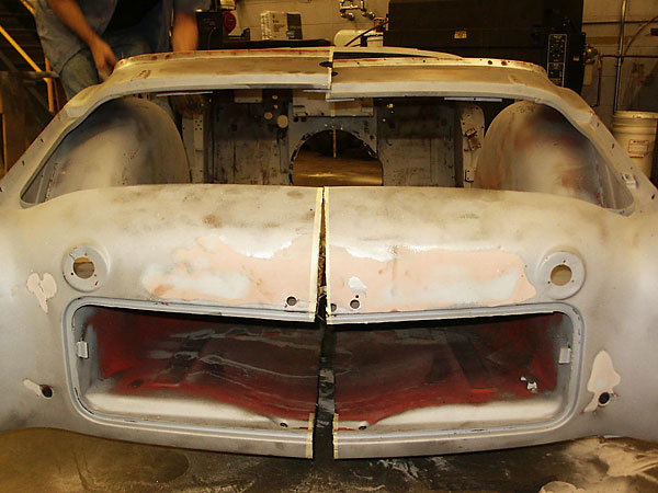
The great thing about history is we can learn from it. I can cut a car �
in half too. With the silent blessing of Alec Issigonis, and the number �
four as the guiding light to glory, I proceeded to "bastardize a �
perfectly good car". �
�
�
 �
�
�
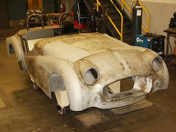
The patient for my surgical procedure was a straight and rust-free �
1958 Triumph TR3 from California. Some would say my actions are nothing �
to be proud of. However, I show no remorse, and stand behind my work as �
the only thing that could have been done to build the ultimate TR3. I'll �
admit there was a moment or two just before "the procedure" where I stood, �
zip-disc in hand, wondering if I were completely insane. Once the first �
incision was made, it was all business. I have never looked back or �
regretted my decision.�
�
I do as much work as I can myself. I am well versed in traditional �
bodywork techniques, and prefer to do things the way the old guys used to. �
For me, every job is a wonderful journey through fields I enjoy walking.�
When people ask me "Don't you just want to get it done and go driving," �
I can honestly reply that the journey interests me more than the destination. �
I enjoy the process as much as the product. �
�
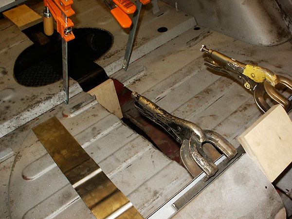
I logged 681 hours of sheet metal work in this project. That includes all �
the cutting, widening and general fabrication of the body. For bodywork, I �
used oxyacetylene gas welding exclusively. Specifically, I used the �
traditional technique of butt hammer-welding with no filler rod to produce �
light-tight joints. This requires simple tools: a size "000" torch tip and �
a good hammer and dolly. If anyone wants to know more about this realm, �
just ask me about it. �
�
�
�
 �
�
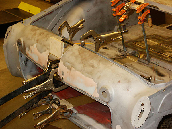
� Steel filler strips were added, of course, right up the centerline of the � body and even through the dashboard. Each filler strip matched the profile � to its right and left in all respects including curvature, bends, ribs, etc. � From the hood rearward, the strips were four inches wide, but forward of � the hood I decided to add only three inches along centerline, and to add � a half inch along each side. [Editor's note: It's hard to see in the photos, � but this added steel is just inboard of the fender seam. It's about � two inches outboard of the headlights.] Because the hood itself was widened � by four inches right up its middle, some re-contouring of both hood and nose � was required to bring curves and edges into alignment. �
��
Enjoying this article? Our magazine is funded through the generous support of readers like you!
�
To contribute to our operating budget, please click here and follow the instructions.
�
(Suggested contribution is twenty bucks per year. Feel free to give more!)�
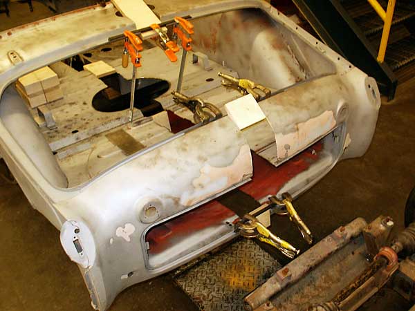
� I used an extra trunk lid to fill-in the bodywork behind the seats. I feel � this space is useless for the original advertised function of occasional � seating. As well, it offers no security for cargo storage. By closing this � in, I was able to reverse the fuel tank and gain nearly a foot of trunk space. � Rollover protection hoops project through this deck and I decided to relocate � the fuel filler to this area too. The roll hoops also have brace tubes on � either side of the car running from the front floor pan frame mounts, over � the rear wheel arches, and into the trunk where they ties into the floor at � the back. This system forms sort of a truss arrangement that really adds � rigidity to the body. �
��
�
�
 �
�
 �
�
�
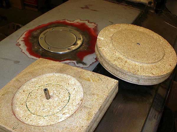
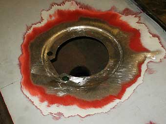
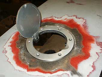
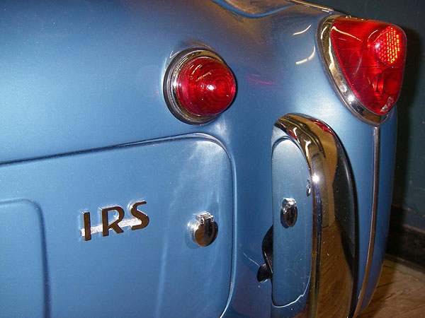
The fuel filler door is a Ford Mustang aftermarket part, with the Ford �
logo carefully filed-off the inside of the lid. The filler cap lives below �
this and is the original Nissan part connected to the TR3 tank. Since I'll �
be using aftermarket gauges the original Triumph fuel sender (resistance �
range = 0-9 Ohms) was discarded in lieu of a VDO universal fuel level sender.�
�
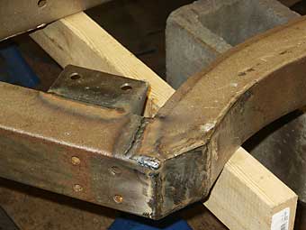
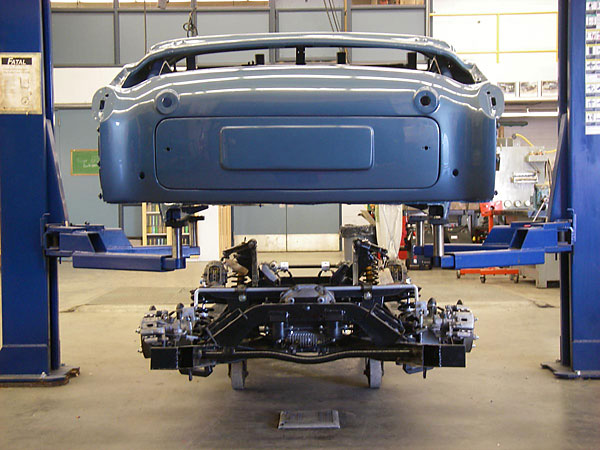
Turning attention to the chassis... I welded-over all Triumph's original �
frame welds. In comparison to the earlier TR3 frames, the TR6 welds are �
much poorer. Almost all of them were "cold". After sorting this out, the �
frame was sent off for powder coating.�
�
 �
�
�
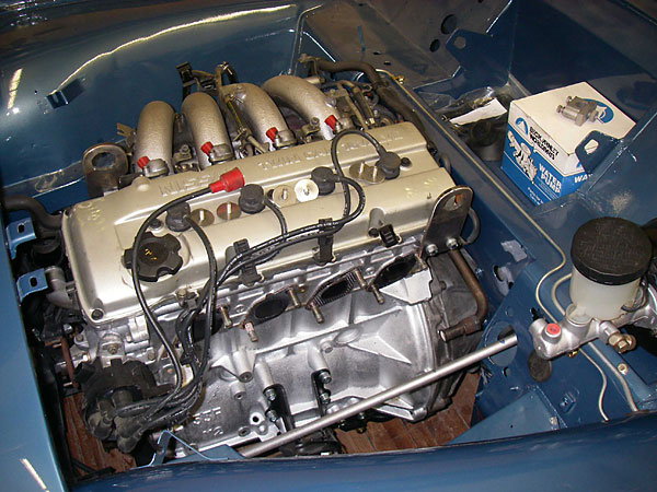
The running gear is from a 1991 Nissan 240SX. The engine is a 2.4 liter, �
16-valve OHC electronic fuel-injected design with about 168 HP through the �
"SX" 5-speed box and limited slip differential. That's about a 68% increase �
in power over the original Massy-Fergusson tractor derived power plant that �
used to pull the TR3 around. One of the founding concepts in this project was �
to run clean with good power, reliability and economy. The engine has full �
emission control features including catalytic converter, O2 sensors, etc. �
included in the installation. �
�
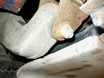
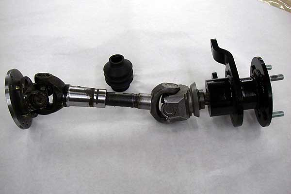
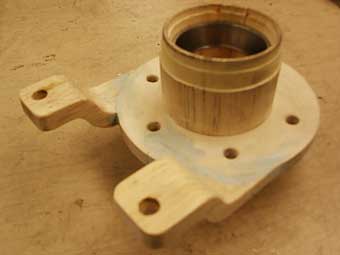
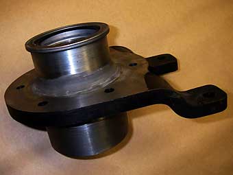
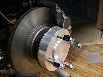
To keep the power reliable at the stern, I used Corvair spindles running �
in custom-built hubs. This isn't a new idea. Back in the day, Corvair or �
Mercedes spindles were commonly used on racing Triumphs because the TR6 �
axles would break due to poor design. (The TR6 axle ends conclude in a long �
taper with a keyway cut along that taper. When free-play develops between �
the axle and the hub assembly, the axles break as the hardened key impacts �
its way to victory over the softer axle material.) There is a U-joint that �
will connect the Corvair yoke to the TR6 yoke, thank God. The inside of the �
trailing arms needed some slight relieving, but it all worked out neat in �
the end.�
�
�
 �
�
 �
�
�
The Nissan differential is the limited slip unit referred to as the "R200". �
After looking at Goodparts' conversion kit to mount the differential to the �
TR6 chassis, I decided to make my own. The Nissan driveshaft assembly was �
shortened to match the new driveline length. Other rear modifications �
include a tube shock conversion located within the spring, as well as a �
custom sway bar mounted from above. I have fitted in the Goodparts rear �
camber adjustment system between the frame and trailing arms to be able to �
flaunt how much rear camber the ultimate TR3 can have.�
�
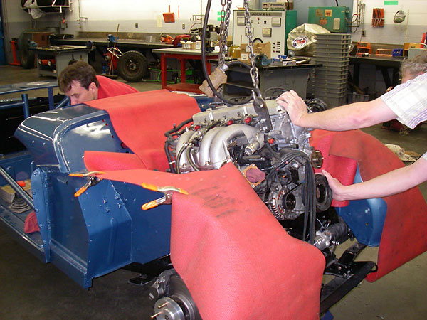
The engine sits very well in the new engine bay with no interference issues �
with steering, exhaust, firewall etc. I made custom frame brackets to mount �
the engine and was able to use the stock Nissan mounts. �
�
�
�
 �
�
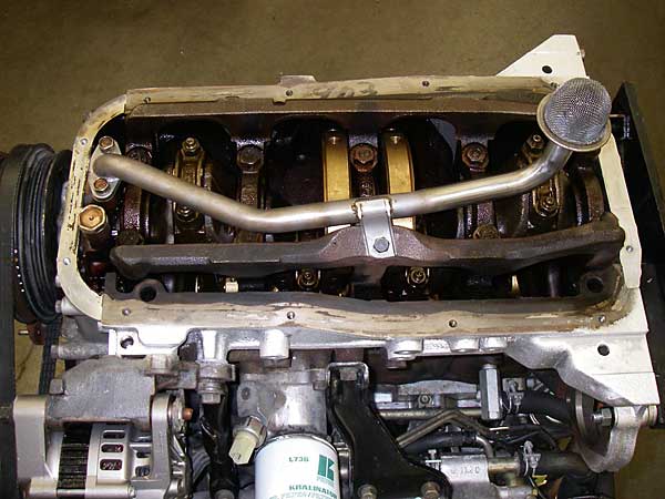
� The engine oil pan was, however, an issue. The Nissan 240SX has a front sump oil � pan and I needed a rear sump to clear the front frame cross-member. I thought this � would be easy, as the same engine was used in Nissan trucks like the Frontier � with a reversed pan. However, in truck applications the front timing-chain cover � is a different shape and this forms the front edge of the pan shape. I used both � pan types, taking the original front sump, cutting it down and grafting it to � the back half of the truck pan. I re-routed the oil pick-up to the back using a � variety of piping from both set-ups welded into the correct shape. �
�� The radiator is an all aluminum, three-row core, cross flow unit, for VW racing � applications from Summit Racing. The (pusher) fan set-up is from Perma-cool. � Exhaust manifold is stock, except for the removal of casting marks and the � standoff bosses that the original heat shield bolted to. I had the manifold � ceramic coated, with the effect of reducing the running temperature of this � part by 300 degrees (and because it looks cool!)�
��

�
 �
�
 �
�
�
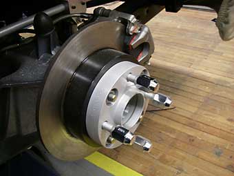
The front brakes feature Toyota 4-runner four piston calipers and Toyota �
Cressida vented rotors. Nissan 240SX discs were installed in the rear. The �
Toyota 4-runner calipers literally bolt right on with no modifications. Fitting the �
Cressida rotors required that the TR3 hub's outer shoulder be machined smaller �
by about 0.020". �
�
Because I'm running four-wheel discs, I needed power assist. The smallest brake �
booster I found was from a Suzuki Swift. I connected this to a Mazda Miata master �
cylinder. (You should use a master cylinder designed for four-wheel discs if �
that's what you're running.) To keep the same mechanical pedal ratio of the �
Miata, I had to design and build a double-acting swing mechanism to work with �
the TR pedal position. This linkage allows longer lengths, without changing the �
original ratio. A proportioning valve allows adjustable braking bias between �
front and rear. �
�
The 15" alloy wheels are from an early Nissan 240SX. I bead-blasted the �
anodizing off, welded-up some curbing mishaps from previous owners, and had �
them powder-coated. To get my wheel offsets where I wanted them, I machined �
front and rear spacers. The front spacer is 1-1/8" thick and the rear is 3/4" �
thick. The wheels are wearing Yokohama "S Drive" 195/55-R15 tires. Ultimately, �
I think I'll go the plus one route to fill in the wheel wells a bit more.�
�
 �
�
�
The only Lucas electrical components left on the car are lamp housings and �
the windshield wiper motor. The wiper system's worm-gear drive (with spacer �
tubes that can be cut down, lengthened, or even replaced with 3/8" brake line) �
is ideal for being able to move the gearbox units four inches further apart. �
My friend who understands the shortcomings of British electrical systems tells �
me this is where the fire will start in my car!�
�
The steering column is from a TR6, with a modified outer column tube to get �
the right length, and also to eliminate the column-mounted turn signal and �
light switches. The car will use the original TR3 center unit modified to fit �
on the TR6 steering wheel. The seats are from a Porsche 914. It's hard to �
find a good seat that's narrow enough for these cars - even if you've added �
four inches! (Actually, I re-designed the transmission tunnel and driveshaft �
cover to be a structural part of the body, so it is taller and slightly wider �
than the stock arrangement.)�
�
This project is not completed. I still have hundreds of details to address. �
Each feature of the design begins with thought and reflection, followed by �
pencil sketches, measurements, and in some cases full-scale mock-ups, �
templates etc. As each new detail is completed, the car seems to reveal �
another aspect of the whole almost as if the detail were there all along - �
hidden from view. The resulting car is part vision, part inspiration and a �
lot of work! I hope you like it. �
�
�
This article is part one of a two-part series! If you enjoyed this article, you'll enjoy the sequel:
�
Randy Schultz's Triumph TR3 "Plus 4" Project, Part 2�
�
A summary of the car's features and specifications appears here:
�
How It Was Done: Randy Schultz's Triumph TR3�
�
� Photos by Randall Schultz for the British V8 Newsletter. All rights reserved. �