
 �
�
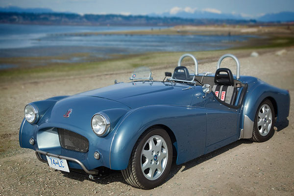
Randy Schultz's Triumph TR3 Plus 4 Project, Part 2
��
as published in BritishV8 Magazine, Volume XVII Issue 1, July 2009�
�
by: Randall Schultz�
�
It's finally finished! After logging over 2800 hours, it's hard to believe �
there is now actually an automobile where there was none before. After the countless �
hours of designing, fabricating, and assembling, all that's left is to actually �
drive and enjoy the finished product. �
�
In an earlier BritishV8 Magazine article, I documented the majority of the build of my �
TR3 Plus 4. (The "Plus 4" part came about because I cut a Triumph TR3 body down the �
center and widened it four inches so it would fit on a later TR6 frame and accomodate �
both the TR6's rack-and-pinion steering and its independent rear suspension.) This �
article is about the final details. It picks up where the first article concludes. �
I've tried to focus on things that might be useful to others who are starting their�
own major projects.�
�
So, where does "part two" of the story logically start?�
�
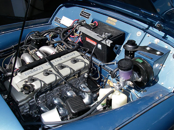
The Nissan engine fired up instantly. However, the first installation problem showed �
up almost as instantly. The return line from the fuel injection system to the tank �
was located too close to the suction line of the charcoal canister, which instantly �
became fuel logged. After replacing the canister and re-routing the canister connection �
point to the fuel tank, that problem was solved.�
�
 �
�

�
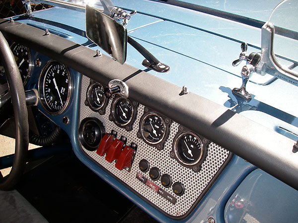
Getting an aftermarket (Classic Instruments) speedometer to work with the Nissan �
PCM was a challenge too. The speedometer is designed to work with a simple digital �
pulse generator, located on the transmission. I initially assumed that the Nissan �
PCM could use the same signal, but in fact it requires a differently "conditioned" �
signal from what the gauge expects to see. A friend who teaches this stuff at a �
local technical college saved the day. We mocked the whole thing up using a drill �
press turning at a known RPM driving the pulse generator, connected to the gauge, �
also connected to a digital readout of the pulse waves. This is how we discovered �
the original pulse to the Nissan's PCM was not the same as the pulse delivered �
to the gauge. Our solution was to strip out the original PC board from the Nissan �
gauge cluster and connect it in parallel with the aftermarket speedometer. People �
who see the completed project rarely realize the research and development involved!�
�
Come to think of it, there were a couple other challenging engine installation �
details to work out. When I reversed the oil pan (see �
previous article) �
I realized that the position of the dipstick would no longer work, because it �
now pointed to the low end of the pan. Because the dipstick runs through the �
engine block, I knew I had an issue. Drilling the block for a new location for �
the dipstick was not going to be an option, so I decided to connect an external �
tube to the side of the reversed pan near the bottom of the pan. Oil in the pan �
would obviously be the same level in the tub, and this became the new home for �
a slightly modified-length dipstick. Putting in the exact capacity oil in the �
crankcase, seeing where it came to on the dipstick and making a line on the stick �
indicating "full" was all I needed. �
�
 �
�
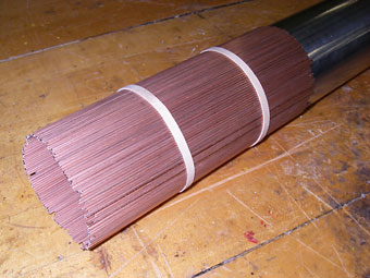
� On the engine's induction side, I designed an aluminum air-box to house the � engine air filter and serve as a connection point for the MAF ("mass airflow") � sensor. Since space was really tight for this, the only point where the MAF could � join the air box was at a corner. To make it even more challenging, the MAF sensor � wanted a round mount section, and the corner of the planned box was square. I � needed to map out the point of intersection where the round tube met the square corner. �
��
 �
�
 �
�
�
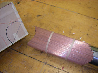
My solution was to construct a simple shop-built layout tool specifically for the �
job. I took a length of the same tubing I planned to use for the actual part, �
surrounded it with as many sixteenth inch welding rod pieces as it took to go �
around its circumferance, and secured the rods in place with a couple of rubberbands. �
The rods extended past the end of the tube by a few inches. Holding the tube at �
the angle and location that I wanted to make the connection, I simply pushed the �
whole affair into the corner of my cardboard mock-up. The rods slid to conform �
with the mating surface, and it was easy to trace out the contour of the �
intersection on the three surfaces that comprised the corner of the box. �
Very accurate cut-lines efficiently facilitated a tight connection. With no �
gaps greater than one sixteenth of an inch, it was easy to TIG weld the parts �
together. �
�
On the engine's other side, I had to create a unique exhaust downpipe arrangement. �
I used the original manifold for space reasons, plus I used the first six inches �
of Nissan's original downpipe (which included the bung for the 02 sensor). As is �
always the case, the required bends to thread from "here" to "there" were a bit crazy. �
�
 �
�
�
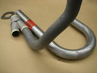
Custom flex-tube tool for exhaust system layout. The tape wraps indicate cut-lines for planned welded joints.�
�
Again, the solution started with a special shop-built layout tool. I went down to the local�
hardware store and bought three feet of water pipe insulation wrap for one inch pipe. �
I then removed the flex pipe from our shop's parts cleaner solvent tank - it's the pipe �
that the solvent comes out of. It can be bent to any configuration required and stay put. �
(Like a gooseneck lamp... there must be a name for this stuff!) Next, I pushed the flex �
tube through the insulation wrap. Presto! The result was a flexible header pipe that's�
prefect for mock-ups. The outside diameter worked especially nicely because I could �
stick one end into the existing downpipe end and model the rest as required. �
�
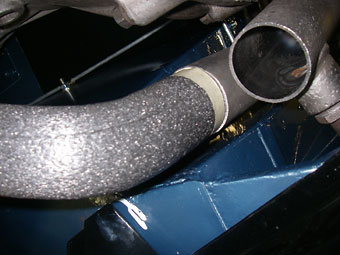
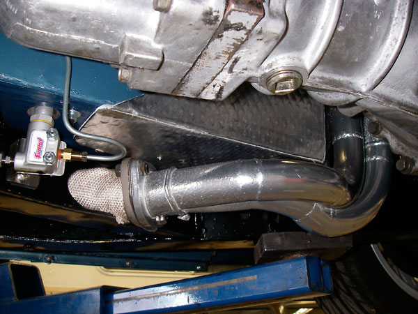
The next two photos show the completed custom exhaust downpipe as finally installed. �
I had both the manifold and the downpipe ceramic-coated; the finish looks great plus �
it's supposed to lower the surface temperature by as much as 300oF. Note �
the self-adhesive mastic sound-deadening sheeting applied to the body in strategic places. �
I learned that the stuff that performs well also costs the most.�
�
 �
�
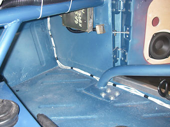
� The collector pipe had to go through the frame. I knew this from the early stages of � the project, and had cut the elliptical holes way back. To retain the strength of � the frame rail, I inserted and welded-in a formed metal pass-thru tube. The collector � is welded directly to stainless flex pipe that is wrapped for heat control. The rest � of the exhaust is hard-mounted and passes through the frame two more times on its way � to the rear muffler.�
��
 �
�
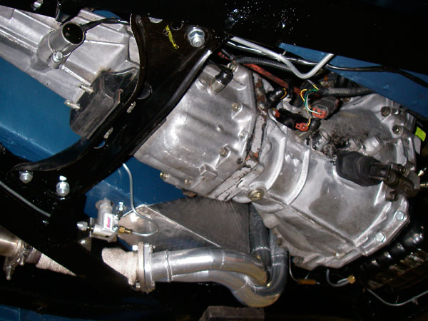
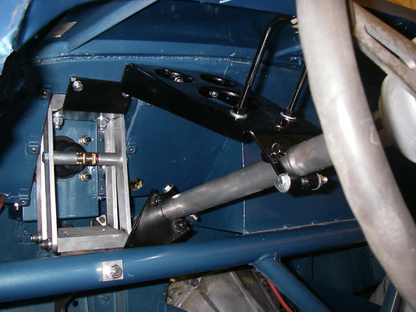
� Incidentally, you can also see the rear brake proportioning valve mounted on the � frame rail. This valve allows front versus rear brake bias to be adjusted with the � turn of a knob. I have this mounted to the frame rail, and the knob emerges just � above the carpet on the driver's side floor. That brings us to the driver's � compartment... (For more information about the brake system, see below.)�
��
 �
�
�
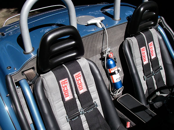
I used Porsche 914 seats because they're well-made, lightweight, and narrow enough �
to fit into tight spaces. However, they gave me problems: their integrated headrests �
looked too modern for my car plus they didn't allow racecar-style dual shoulder �
belts to pass through. I removed the upholstery and cut the fiberglass headrests �
off the Porsche seat frames. At a local junkyard, I found removable headrests �
from a Nissan Quest that looked like they might integrate with the styling and �
functionality I was after. I built a mounting tube assembly and riveted it to �
the fiberglass frames, prior to having the seats reupholstered. Grommets at the �
top of the re-worked seats facilitate headrest removal, and racing shoulder belts �
pass through neatly. Now, the headrests can be adjusted, and they can even be �
removed for installation of a tonneau cover. I didn't have to add ugly bulges �
to the tonneau cover! �
�
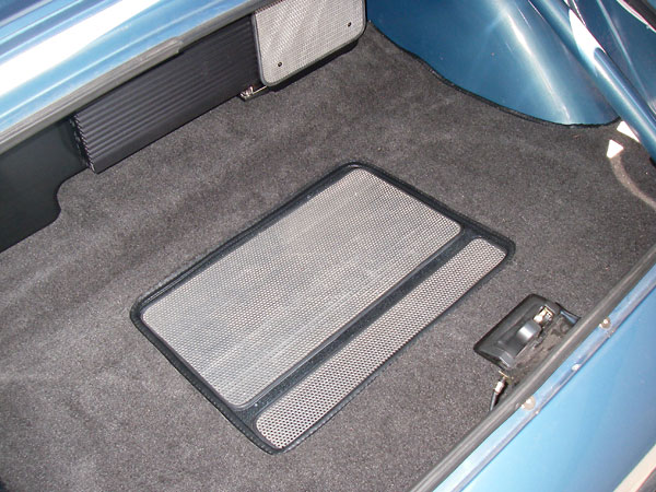
I saved a lot of money making my own patterns for the carpeting. I asked the �
owner of the upholstery company if I could do this and he replied: "as long as �
they fit!" Well no one else cares as much that they do as me, so off I went. I �
used brown paper from a 36" roll and made my patterns to fit edge to edge and �
butts at all corners. The carpet guy said he would decide what overlapped what �
and by how much. When I was finished he came and checked out my work. After �
checking every piece for fit he told me I was hired. We used snaps to hold all �
the horizontal pieces down, so they can easily be removed after an unexpected �
rainstorm or for service.�
�
Enjoying this article? Our magazine is funded through the generous support of readers like you!
�
To contribute to our operating budget, please click here and follow the instructions.
�
(Suggested contribution is twenty bucks per year. Feel free to give more!)�
�
 �
�
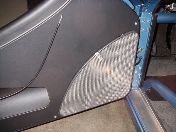
� One product I've used extensively throughout this project is 1/8" perforated � aluminum sheet. This sheet is available with various combinations of hole-size � and spacing, but the options are all 1/8" thick. I used the perforated sheet � between the trunk and seating area, for the speaker grille panels and the � subwoofer grille, for the dash center and heater grille, for the accelerator � pedal scuff panel, and the glove box. It's a soft alloy that cuts easily on a � table saw with a carbide blade, or on a band saw with a skip-tooth blade, and � it sands easily too. The holes provide easy opportunities for mounting the � panels. Did I mention I love this product? The only challenge is how to trim � cut edges for a finished appearance. My solution was to take engine vacuum � tubing and carefully cut along the length to create inexpensive, custom, flexible � rubber trim. I simply glue the trim to the edge of the panel using weatherstrip � adhesive. This works very well, but can be a bit messy until you get the hang � of it. �
��
 �
�
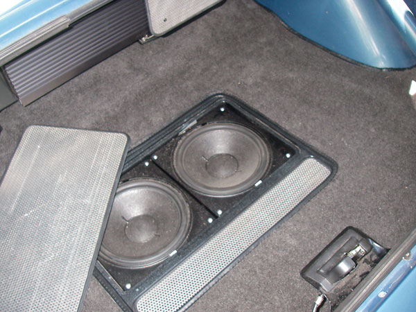
� I really enjoyed designing and making a subwoofer box for the audio system. I � selected two 8" drivers, and I decided to build a ported enclosure for efficiency.� From the published specifications of the drivers, I calculated the optimal volume � for the enclosure. (By optimizing enclosure volume and port size, low frequency sound � from the port is phased to reinforce the bass output of the drivers. Ported � subwoofers can thus be made louder than similarly sized closed box subwoofers.� However, to do the job right you need to know the natural frequency of whatever � drivers you use.) �
��
 �
�
� My first plan was to build a removable speaker enclosure and attach it behind � the fuel tank. I had the room, as mentioned in the previous article, having � re-located the tank closer to the seats by in-filling the bodywork and turning � the tank 180 degrees. This mod gave me another 12 inches of trunk space. The � issue was that I really hated to give it up for a subwoofer box! The solution was � to use part of the spare tire compartment to create the sub volume. In the TR3, � the spare tire lives in its own space, just under the trunk floor, but completely � separate from it. I determined the size of the sub's front panel based on calculating the � volume of the spare tire cavity and matching it to the required volume for the � subs. This panel was cut out and replaced with a 3/4" aircraft plywood panel � mounted under the trunk floor panel. This was sealed and screwed-down from the � top. The drivers were flush mounted in the panel and covered with a grille. � The required dimensions of the sub still allowed for about 8 inches of space � for storage of items such as the jack, oil, and - you guessed it - a can of � "Fix-a-Flat". The division between the two spaces was another carefully fitted � and sealed piece of aircraft plywood. Anyone using any form of wood in builds � should be sure to seal all surfaces with durable coatings, not just visible surfaces. �
��
 �
�
�
I wanted a remote/hidden trunk release that could be actuated from inside the �
car. The wrecking yard once again provided a neat solution. Many early to mid-90's �
Honda models use a cable-operated trunk lid release mechanism. A keyed lock is �
part of the release mechanism inside the car. It's very cool, and totally adaptable �
to custom applications.�
�
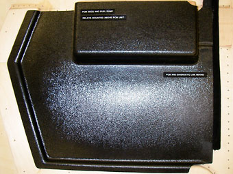
I mounted the Nissan PCM on the passenger foot-well. The wiring harness runs from �
the main breaker panel to the rear of the car through this area too, so I considered �
making a protective aluminum cover for these components. However, I was concerned �
aluminum wouldn't match the rest of the car's interior. �
�
 �
�
�
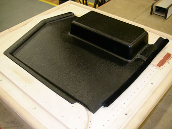
The vacuum-formed panel is 1/8" thick black ABS plastic with a gloss "hair cell" finish on one side.�
� My solution was to make a formed panel from rugged one eighth inch thick ABS plastic. � I borrowed a vacuum-forming machine for the job, and made a mold in the shape � I wanted out of wooden blocks attached to plywood. Using putty, these blocks were � filleted where they met the board. I drilled a series of eighth inch holes through the � base-board about one half inch apart near these filleted corners. The board was sealed � onto a vacuum box mounted underneath. The heated ABS sheet was then placed over the � form, held by a perimeter framework. The vacuum machine allows the entire form and � vacuum box to be raised up and into the softened plastic at the same time that vacuum� is applied. Excess material was then trimmed off and the panel fitted in place. � I'm happy with the result, and would encourage others to experiment with these techniques.�
��
 �
�
�
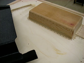
I constructed the male wooden form shown here. You can see the drilled holes that the vacuum pulls through.
�
About 7 degrees of draft angle is built-in so that molded parts can be pulled out of the mold.
�
(Note: the part has been removed, trimmed, and placed back in the mold for the photos shown at right.) �
� Vacuum forming machines are relatively simple and can be built at home. � I imagine using a modified electric stove for the heat source and building a roll � out rack to clamp the heated ABS sheet. A vacuum pump with about 20 inches of � vacuum is needed, as is a way to raise the mold up into the softened plastic � as the vacuum is applied. Vacuum forming materials are purchased in flat sheets. � They're available in a wide range of thicknesses, colors, materials, and finishes. � I'm sure vacuum forming would be a great process for many interior molding details. �
��
I had a lot of issues getting ride height and fender well clearance just right. �
I ended up with custom springs that have worked out well. I'm using stock 15" �
Nissan 240SX alloy wheels with Yokohama "S Drive" 195-55R performance radials. �
I wanted a taller tire, but I couldn't find one that offered comparable performance,�
so from my aesthetic point of view the car is too low by about an inch. The �
easiest fix would be a taller tire, as I have enough clearance in the fender �
openings. I could potentially use a larger wheel, but I really don't like the �
current trend of driving on rubber bands!�
�
On the road the car handles much like a set-up Triumph TR6, which it is. The �
stiffer springs and shocks, as well as the large front sway bar really flatten �
out body roll. The adjustable rear camber set-up by Richard Goodparts works �
really well and setting it up was absolutely easy. This system also allows �
for slight changes to ride height by equal adjustments at both points. The �
shorter front springs did not allow me to get exactly the front geometry I �
wanted. I was after 3/4o negative camber and even with all the �
lower control arm shims out, my front camber was still a little too negative at �
1.2o. I wanted 3o caster, but had to settle for �
2.2o. The TR6 front suspension doesn't allow for big changes, and �
the only way to get more out of it would have been to design and make an �
adjustable upper control arm mounting system. Perhaps down the road... The �
solid steering rack blocks I made up did exactly what they were supposed to �
do: they translate road feel back to the steering wheel. The Bilstein custom �
rear shocks by work great too (and the shop that provided them was quick and �
easy to work with.) �
�
The brake system works very well too! Frankly, the TR3 Plus Four has a whole lot �
of braking capacity for such a light vehicle: as shown in some detail in the �
previous article, �
Toyota Four-Runner front brakes squeeze Toyota Cressida vented rotors, and �
Nissan 240SX disc brakes are installed at the rear. What about the rest of the �
brake system?�
�
�
This unusual brake pedal mechanism kept pedal effort (i.e. mechanical advantage ratio),
�
pedal stroke, and master cylinder piston travel all similar to stock. �
�
A Mazda Miata master cylinder and a Suzuki Swift booster are actuated with a �
custom pedal linkage. �
�
As shown earlier in this article, a Summit Racing proportioning valve is �
accessible from the driver seat. It acts on the rear brake circuit, and facilitates �
tuning of front-to-rear brake bias on the fly (for example, to accomodate a change �
in fuel load or adapt for wet road surfaces.) �
�
�
parking brake cables
�
�
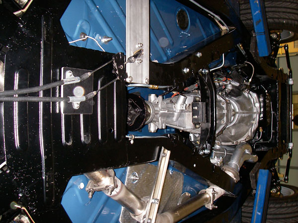
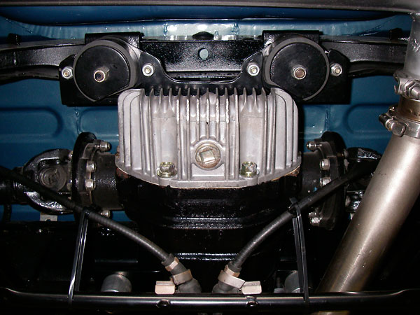
Nissan differential on custom fabricated mounts, with adapter plates that mate to regular TR6 halfshafts.�
�
Acceleration is brisk. The Nissan KA24 engine has a lot of bottom end torque, �
and it's not afraid to rev up to the mid 6000's. The engine's power is delivered very �
smoothly in comparison to the original Triumph tractor engine, and the 5-speed Nissan �
transmission is wonderfully smooth too. �
�
The car gets a lot of attention on the road. I need to rehearse some fast �
answers to what are becoming popular questions. What do you say when people �
ask "What kind of a car is that?" or says "I used to have one just like that!" �
How about: "It's so nice to see one of these restored back to original." �
Should I make or break their day?�
�
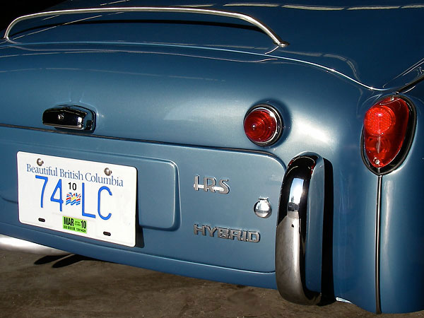
My conclusion is that we are building hybrids. With this term now applied �
through popular culture with respect to multi power sources within the �
same vehicle, the real definition of the word has been clouded. And �
besides hybrid sounds so much better than bastard!�
�
�
Hybrid \ˈhī-brəd\ n. 1: a crossbred animal or plant; an offspring of two different breeds, genera or varieties. �
�
�
This article is part two of a two-part series! If you enjoyed this article, you'll enjoy its predecessor:
�
Randy Schultz's Triumph "TR3 Plus 4" Project, Part 1�
�
A summary of the car's features and specifications appears here:
�
How It Was Done: Randy Schultz's Triumph TR3�
�
� Photos by Randall Schultz for the BritishV8 Magazine. All rights reserved. �