�
 �
�
�
�
�
�
�
�
�
�
� by: Curtis Jacobson�
� In 1957 Sterling Moss piloted "The Roaring Raindrop" (aka EX181, as photographed � by Bob Elwin at the "Goodwood Revival"), to a 1.5L Class world-record speed of � 245.64mph, averaged over a "flying kilometer", on the Bonneville Salt Flats. � Two years later, after engine modifications, Phil Hill set a new speed record � in the car at 254.91mph.�
� None of my readers are likely to see those speeds in a modified MGB, even with � three times EX181's engine displacement. The most obvious limiting factors are: � "coefficient-of-drag", "frontal area", and "availability of salt flats". Syd Enever's � design is exceptionally sleek, with a coefficient-of-drag of just 0.000292. Also, � it only stands 39.25 inches tall at the top of the driver's "bubble". (It's about � 30 inches tall across the body. I haven't found a width or area measurement.) At � just half EX181's record speed, our little cars exhibit scary "light steering" due � to aerodynamic lift. If you ask MGB V8 owners what aerodynamic modifications � they've made, the answer you're most likely to hear is "I fitted an air dam."�
�
�
�
 �
�
Practical Automotive Aerodynamics for MGB V6 and V8 Builders
� The British V8 Newsletter, Volume XV Issue 1�� by: Curtis Jacobson�
� In 1957 Sterling Moss piloted "The Roaring Raindrop" (aka EX181, as photographed � by Bob Elwin at the "Goodwood Revival"), to a 1.5L Class world-record speed of � 245.64mph, averaged over a "flying kilometer", on the Bonneville Salt Flats. � Two years later, after engine modifications, Phil Hill set a new speed record � in the car at 254.91mph.�
� None of my readers are likely to see those speeds in a modified MGB, even with � three times EX181's engine displacement. The most obvious limiting factors are: � "coefficient-of-drag", "frontal area", and "availability of salt flats". Syd Enever's � design is exceptionally sleek, with a coefficient-of-drag of just 0.000292. Also, � it only stands 39.25 inches tall at the top of the driver's "bubble". (It's about � 30 inches tall across the body. I haven't found a width or area measurement.) At � just half EX181's record speed, our little cars exhibit scary "light steering" due � to aerodynamic lift. If you ask MGB V8 owners what aerodynamic modifications � they've made, the answer you're most likely to hear is "I fitted an air dam."�

�
That's well and good. Some air dams have proven effective at improving high �
speed stability. Some reduce drag. Some duct air better into the cooling system. �
Some air dams even provide holes from which you can duct air to help cool the �
brakes. But this article isn't about air dams. That would be an excellent topic �
for a future article. �
� There are many other practical, inexpensive aerodynamic improvements to consider � for our cars. This is The British V8 Newsletter's first article on aerodynamics, � intended to present a little background plus some measurement and analysis � techniques, but it's certainly not a sweeping overview. Rather, it started and � remains a response to one deceptively simple little question. Someone asked me: � "How much power can you get from cowl induction?" �
� I would have been the first to concede there's probably not much power to be made � from cowl induction. Still, it's an interesting question. Answering it properly � requires breaking the question into two:
� a) What benefit can be gained by pressurizing charge-air via � air ducting alone?
� b) What additional benefit can be facilitated if the ducted-in � air is cooler (and thus more dense) than un-ducted air?��
�
� My friend Bill Wardlow at "The Motorway Ltd." in Fort Collins, Colorado told � me about an experiment he once did with an MGA. He taped short pieces of thread � along the hood and fenders and observed how they behaved as he drove the car. � (Magnetic tape from an old cassette tape works well for this too.) One surprising � observation was that air seemed to flow OUT of the oval-shaped MGA fender vents � at low speeds (say under 25mph) - but at higher speeds, air was sucked INTO them!�
� Why does air flow? The short answer is that air is constantly being pressurized � or depressurized. Air flows as a "fluid" from areas of higher pressure to areas of � lower pressure. �
� Cowl vents like the ones MGB's use for cabin ventilation work because, when the � car moves, turbulent air builds up pressure at the base of the windshield. Cowl � induction, as historically promoted on Chevrolet muscle cars, is an old trick � whereby high pressure air at the base of the windshield is ducted into the � carburetor to achieve some pressure boosting effect. Cowl induction is essentially � just a variant of "ram air effect", a term more often associated with � forward-facing grilles and "hood scoops". �
�
�
�
� There are many other practical, inexpensive aerodynamic improvements to consider � for our cars. This is The British V8 Newsletter's first article on aerodynamics, � intended to present a little background plus some measurement and analysis � techniques, but it's certainly not a sweeping overview. Rather, it started and � remains a response to one deceptively simple little question. Someone asked me: � "How much power can you get from cowl induction?" �
� I would have been the first to concede there's probably not much power to be made � from cowl induction. Still, it's an interesting question. Answering it properly � requires breaking the question into two:
� a) What benefit can be gained by pressurizing charge-air via � air ducting alone?
� b) What additional benefit can be facilitated if the ducted-in � air is cooler (and thus more dense) than un-ducted air?�
A Few Alternative Places to Draw Air for Your Engine
�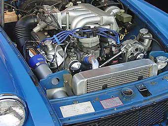 � Kelly Stevenson's air intake is ahead of the radiator. | �
� | 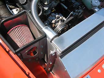 � Bill Guzman's air intake is beside the radiator. | �
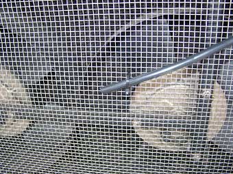
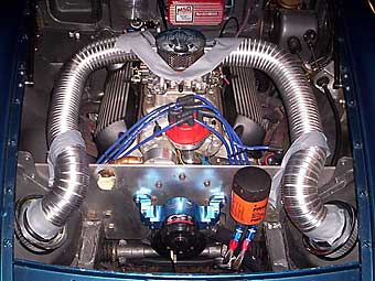 � Jim Strait experimented with drawing air from the wheel wells. | �
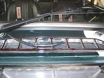
� | 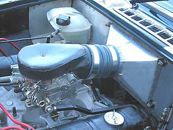 � Curtis Jacobson's air intake is through the MGB cowl vent. | �
Cowl Induction and Ram Air Effect
� When cars move relative to the air around them, air is inevitably pushed around. � If it can smoothly slide away without much turbulence, so much the better, right? � If we had a "wind tunnel", we could put our cars in it and experiment with various � body modifications. We might like to observe how smoke-streams flow over surfaces. � Are they "laminar" or turbulent? Where and how do they "detach"? Forget about it! � No one I know has a wind tunnel, so we just do the best we can. �� My friend Bill Wardlow at "The Motorway Ltd." in Fort Collins, Colorado told � me about an experiment he once did with an MGA. He taped short pieces of thread � along the hood and fenders and observed how they behaved as he drove the car. � (Magnetic tape from an old cassette tape works well for this too.) One surprising � observation was that air seemed to flow OUT of the oval-shaped MGA fender vents � at low speeds (say under 25mph) - but at higher speeds, air was sucked INTO them!�
� Why does air flow? The short answer is that air is constantly being pressurized � or depressurized. Air flows as a "fluid" from areas of higher pressure to areas of � lower pressure. �
� Cowl vents like the ones MGB's use for cabin ventilation work because, when the � car moves, turbulent air builds up pressure at the base of the windshield. Cowl � induction, as historically promoted on Chevrolet muscle cars, is an old trick � whereby high pressure air at the base of the windshield is ducted into the � carburetor to achieve some pressure boosting effect. Cowl induction is essentially � just a variant of "ram air effect", a term more often associated with � forward-facing grilles and "hood scoops". �
�
�
How effective? As a starting point, a physics or fluid dynamics teacher would tell �
you ram air effect is a function of vehicle speed. Applying Bernoulli's Equation, �
one can easily calculate the maximum pressure stationary air can apply to a moving �
object. Drive faster, and the pressure goes up, and in fact it goes up increasingly �
quickly. The real-world problem is that Bernoulli's Equation only gives us a �
theoretical maximum. To know how much ram air effect is achievable on a given �
induction system, it's easiest and best to take actual measurements. �
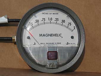
� Dwyer-Magnehelic Differential Pressure Gauges are simple, economical, mechanical � tools with which one can test the potential efficacy of various kinds of vents. � The gauge is most useful for "non destructive" preliminary testing - we don't have to � actually install the vents to get a good idea how well they would perform. One could � also use this gauge to optimize placement of vents, to analyze pressure drops in � ductwork, to check dirt level in an air filter, or to compare heat exchangers (such� as radiator cores.) �
��
 �
�
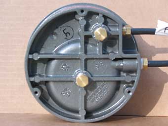
� Magnehelic gauges are 4.5" in diameter and have two sets of 1/8" NPT ports.
� �
I purchased a Magnehelic Differential Pressure Gauge to play with. They're quite �
expensive if purchased new, but surplus gauges routinely sell on eBay for less than �
$25. These gauges are made and calibrated for use at many different pressure ranges, �
so it's important to pick one with an appropriate range and scale. I've found that a �
gauge that reads from 0 to 2 "inches of water" is convenient for measuring �
pressure differences around the body of an automobile.�
��
 �
�
� 1/8" I.D. crush-resistant PVC hose is routed from the gauge to areas of interest.
� �
To help evaluate potential places to draw air for MGB engine installations (and �
also to learn more about cooling system airflow) I routed hoses from the dashboard �
area to four areas of particular interest: (a) in front of the radiator, (b) inside �
the engine compartment, (c) under the wheel well, and (d) above the cowl vent. �
� The gauge can only compare two pressure levels at one time, and the user needs to plumb � the higher-pressure area to the "high" port on the gauge. (Versions of the gauge are � also made with a centered-needle which can read positive or negative differentials.)� For these tests I would need to disconnect and reconnect hoses at the gauge multiple � times. I chose to start by comparing all four "areas of interest" to cabin pressure. � All tests were made with my MGB-GT's windows rolled-up (and with duct tape sealing a � few known air leaks). Primarily to make sure my data wasn't screwy, I also made test � runs with the gauge connected for direct comparisons between front-of-radiator vs. � engine-compartment, cowl-area vs. engine-compartment, and engine-compartment vs. � wheel-well. The columns of hand-written data were a little overwhelming, but they � proved reassuringly consistent. �
� The air pressure test results below are the actual measurements made while driving � my 1971 MGB-GT on Interstate 25 in Colorado between Longmont and Fort Collins. Our � elevation is in the ballpark of 5300 feet above sea level. Air temperature was in � the low sixties and humidity was very low. See below for further details about the � test vehicle.�
� There was only light traffic while I was testing. I was careful to avoid following � other vehicles because their presence tended to make gauge readings erratic. In a � couple areas the highway crests small hills or ducks into small valleys. These also � tended to cause erratic readings. Although the gauge needle was never completely � still, I tried to only record relatively stable readings. �
��
�
� �
� where: hp2 = the new horsepower at density d2
� hp1= the old horsepower at density d1�
� Although "density" and "pressure" aren't interchangeable terms, they are closely � related and for practical purposes we can cheat a little...�
� To quickly estimate what power gain might be feasible from utilizing � ram-air to achieve a modestly pressurized air/fuel mixture, we can simply look � at a ratio of relative induction air pressures. Standard air pressure at sea � level is defined as "one atmosphere", which is commonly measured and agreed to � be 14.7psi. However, I took my pressure differential measurements near Denver � Colorado, the "mile high city". At our altitude ambient air pressure � is only about 83 percent of that at sea level - approximately 12.2psi. �
� Remember, I measured the "boost" pressure in front of the radiator (at 70 MPH) � to be 0.051psi. �
� p1 = 12.2psi�
� p2 = 12.2psi + 0.051psi�
� p2 / p1 = (12.2psi + 0.051psi)/12.2psi = 1.0042�
� This quick calculation indicates that the maximum realistic horsepower � benefit one should expect from ram-air effect on an MGB at 70MPH is � in the ballpark of 0.42 percent. �
� Disappointing. �
� A few words of meager consolation: some people have criticized cowl and ram-air � induction systems on hot-rods because they believe these systems might cause the � engines to run very lean at high road speeds or very rich at low road speeds, � depending on how you tune the engine. In practice, these concerns are � unwarranted for British sports car enthusiasts precisely because cowl and � ram-air induction systems simply aren't that effective. Ram-air induction � certainly is highly effective on purpose-built race cars that achieve � much higher speeds than I tested. �
� On the other hand, a legitimate concern with cowl and ram-air induction systems � is they can cause engine damage in the rain or when driving on wet roads. They � MUST have an effective air-water separator. A very little bit of water won't � hurt most engines (and it might even help sometimes,) but a big gulp of water � will cause catastrophic engine failure! Water can also damage air filters.� �
� The test results indicate vents in the inner fenders would enhance airflow � through the radiator at cruising speed because air pressure is significantly � lower in the wheel wells than in the engine compartment. �
� I was curious to see whether electric cooling fans help or hurt at various � speeds. My fans are switched on-and-off at the dashboard, not with a thermostat, � so it was easy for me to test this. With the Differential Pressure Gauge I � didn't see a noticeable effect at 60 MPH, but at 70 MPH switching "on" the � electric radiator fans slightly reduced pressure-drop (and thus airflow) � across the radiator core. �
� Standard Disclaimer: your results will vary. Results will vary from car-to-car � based on factors such as roadster-vs.-GT (windshield rake and height are � different), early-vs-late model (for many obvious reasons), whether an air dam � is fitted, and by the amount of air resistance provided by various different � radiator cores.� �
� If you have a good grasp of algebra, it's possible to estimate an answer based � on the classic work of Charles, Boyle, and Avogadro. You may recall from physics � class that the "Ideal Gas Law" is usually expressed as: PV = nRT
� where: P = pressure, V = volume, R = the gas constant (about 287.05 for dry air), T = temperature ("absolute"),
� and "n" = number of moles... � which is related to the number of air molecules, an indication of the mass of the air.�
� I'll stop right there! If you want to know more about applying the Ideal Gas Law, � I strongly suggest you drink two cups of coffee and go to � Richard Shelquist's � exceptional explanation of air density calculation techniques. I found � Richard's website while running down a tip from British V8 contributor � Greg Fast (an engineer at Valeo Climate Controls) about "SAE J1349". �
��
�
� I learned from Greg that the Society of Automotive Engineers (SAE) has published � industry standards for normalizing dynamometer measurements so that engines and � related systems tested in one set of atmospheric conditions can meaningfully be � compared with tests taken under different atmospheric conditions. The SAE J1349 � standard provides us with a powerful tool: a mathematical formula into which we can enter � air temperature, "altimeter setting" (which we can get daily from online aviation � weather reports), dew point (a measure of humidity), and altitude. If we provide � these four measurements, SAE J1349 will allow us to calculate "relative horsepower" � as a percentage of "rated horsepower". If we plug in two different temperatures, � we'll get out two different relative horsepowers. Comparing them should be one � reasonable way to estimate the potential benefit of cold air induction. �
� So, conveniently, Richard Shelquist's website also provides a handy � SAE J1349 Engine Tuner's � Calculator! While playing around with the calculator, I noticed that Richard � is my neighbor here in Longmont Colorado. I called him up to discuss how to � properly use the tool. Richard advised: "For proper comparison with the established � standards, the air temperature should be the actual air temperature going into the � engine (that is, the air temperature immediately after any air filter)." �
� I plugged a bunch of number combinations into the calculator. For example, assuming � ducted-in air at 64° F, a 30 in-hg altimeter setting (suggested by Richard), 45° � dew point and 5100 feet elevation, the relative horsepower would be 82.9 percent. � Substituting an engine compartment temperature of 160°, relative horsepower would � be 75.3 percent. Applying these percentages, an engine with an SAE rating of 200 hp � would actually produce 165.8 hp when fed cool air versus 150.6 hp with warmer air.� That's an impressive 15.2 horsepower increase, and a full ten percent improvement! �
� I can already anticipate some of the questions... How hot is the air under the � hood when the car is actually moving? How much temperature rise occurs in the � cold-air induction system pipe? Just because you supply the carburetor cooler � air, can you prove the air is still cooler below the carburetor? Don't you have � to put the carburetor in an insulated box? What about the temperature of the fuel � supply? Isn't the denser air going to screw up your stoichiometric equilibrium? Etc. �
� I decided to scratch a little deeper. To get started, I first bought some � relatively inexpensive tools. A dynamometer would have been very nice, but I � don't know anyone who has one. For that matter, a "G-Tech Pro" would be helpful... � but even that's outside my budget right now. I chose instead to go on eBay � and pick up a couple Fluke K-type thermocouples and an adapter for reading � them with my trusty multimeter. Although they won't measure power, they might � help us understand the system.
��
�
If you've ever used a digital indoor/outdoor thermometer, you've used a �
thermocouple. The main advantage of the thermocouples I bought is that they �
aren't encased in plastic. Their low mass means gauge readings change quickly �
and accurately. Also, thermocouples can be placed in tight places. I'll find �
lots of uses for these little jewels! �
� The initial temperature measurements below were made in Longmont Colorado on two � mornings in March. Ambient temperature was about 64° F on both days, � and humidity was very low. (The NOAA website reported dew point was 28° F.) � Our elevation is in the ballpark of 5100 feet above sea level. Due to differences � in conditions, your results would probably vary. For further details about the � test vehicle, please see below.�
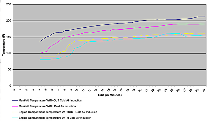
� The initial test procedure was pretty simple (if arbitrary)... the "cold" engine � was started and allowed to idle normally. Temperature readings were recorded � at thirty second intervals for thirty minutes - long enough for everything to � reach steady-state temperatures. Since the electric cooling fans are manually � operated on my car, I turned them on when the coolant temperature gauge read "190". �
� For the first morning's test the cowl induction system was intact. For the second � morning's test I removed the blue hose, so air was drawn from the engine compartment, � and I blocked off the air filter aperture in the firewall. �
��
� �
What does this graph mean? First of all, it shows that the underhood temperature �
of a stationary MGB V8 will come to a stable temperature over time. That temperature �
(e.g. about 160°) is a realistic starting point for discussion, although the �
air temperature under the hood will certainly drop when the vehicle is in motion and �
(jumping ahead) it will certainly spike higher when a working engine first comes to �
a stop.�
� This chart also shows that the temperature of the air/fuel mixture (aka "charge air") � inside the intake manifold runner can be significantly and reliably lower on a car � with cold air induction. From the nine-minute mark onward, the charge air � presented for combustion was consistently about 18° F cooler when cold air � induction was fitted. Depending on your perspective, the temperature differences � may be more or less than expected. �
� We clearly demonstrated something important: "Colder air in" results in "colder air out". �
� Considering that under-hood air temperature rose to over 150° F (i.e. 86° � over ambient), I expected to see a bigger difference between the two charge air � temperature curves. At the end of the first morning's test, air was rising from � 64° F to 190° F within the induction tract - an increase of 126°. � At the end of the second day's test, air was only rising from 160° F to � 212° F - an increase of only 52°! �
� MGB V6 builder Scot Abbott provided some explanation: "The cooler air will � not so readily vaporize the fuel and hence will be cooled less by evaporation � than the warmer air, which will evaporate the fuel more readily and hence be � cooled more in the process. This would cause a leveling of the temperatures � of the differing temperature air masses."�
� Disappointing. By this time, I was starting to wish this article had been about air dams.�
� I decided to take a drive on rural roads east of town. �
� I actually ended up taking two drives to road test the same two induction � configurations as before. Each drive was about 30 minutes long and included rural � roads with speeds up to 60 MPH and occasional stop-signs and traffic lights. �
� My first observation was that engine compartment air temperature drops steadily � when the car is moving, and rises quickly when the car is stopped, within � predictable limits. During the two test drives I never saw the engine compartment � air temperature go below 90° or above 210°. On average it was about � halfway in between. (Notice that the sensor was located at valve cover height but � above the exhaust headers. This location was chosen because it's approximately � where a round drop-base air cleaner or Holley "Hi-Tek" air cleaner would draw � air from. For road testing the sensor cables were re-routed, through the hole � behind the master cylinders, back into the cabin.)�
� Charge air temperature readings behaved more interestingly. Downstream of the � carburetor, air temperature is clearly and directly affected by fuel flow. (You� might expect higher engine RPM and resulting increased airflow would noticeably � reduce charge air temperature, but that effect is overshadowed.)�
� The first drive was with cold air (cowl) induction. Temperature swung quickly � between 90° F and over 180° F. Readings dropped like a rock during � acceleration, and rose immediately when the throttle was released. They were � much more steady at cruise, typically between 120° and 150°, although � they varied with speed and engine load. At stoplights, charge air temperature � went to about 170° or 175°, and then crept slowly upward toward 190°. �
� The second test drive, with cold air induction disconnected, was more surprising. � Even though engine compartment air temperature was sometimes quite moderate, � and even though I tried all sorts of acceleration rates and throttle positions, � in this drive I never once saw the charge air temperature go below 128° F. �
� Temperatures observed during the two drives are summarized in the following table:�
��
�
� Bottom line? The MGB cold air (cowl) induction system reduced the temperature of the � air/fuel mixture (measured about halfway between carburetor jets and intake valves) in � all tested situations, summarized as follows:�
��
�
� �
� Even though SAE J1349 was developed for comparing temperatures UPSTREAM of the induction � system - substituting the wide-open-throttle temperatures we observed INSIDE the number � "1" intake runner is instructive if only because it provides a very "conservative" � system performance estimate to contrast against the preliminary numbers we started � with (above). �
� You can use Richard Shelquist's nifty calculator... or just go straight to the SAE J1349 correction formula:�
� hp2 = hp1 * [1.18 * (T2a/T1a)0.5 - 0.18]
� where: hp2 = the new horsepower at temperature T2a
� hp1 = the old horsepower at temperature T1a
� T1a = the absolute temperature of the fuel / air mixture provided by cold-air induction
� T2a = the absolute temperature of the fuel / air mixture provided by conventional induction
�
� When accelerating at wide-open-throttle: �
� T2a = 587° R�
� T1a = 550° R�
� 1.18 * (T2a / T1a)0.5 - 0.18 = 1.18 * (587° R / 550° R)0.5 - 0.18 = 1.038�
� This quick calculation, based on actual measurements on a typical spring day, � indicates that cold air induction on my V8-powered MGB should be providing � at least 3.8 percent power increase at wide open throttle. �
� Cold air induction systems provide their maximum performance advantage after � leaving a stop, when engine compartment air is relatively high, and when the � vehicle is accelerating at wide-open-throttle. �
� In combination with ram-air effect at high speeds (e.g. at the dragstrip) the � potential performance benefit may temporarily be higher. (Add the 0.47 percent � "boost effect" estimated above to the 3.8 percent estimated here.) �
� On a car like Kelly Stevenson's Ford 5.0, fuel-injected, V8-powered MGB (shown above), � a 4.3 percent gain translates to over eleven horsepower. That's a lot of benefit � from simply fitting a straight, foot-long aluminum tube!�
� It would be wild over-selling to call cold air induction a "poor man's supercharger"� based on the benefits we observed, but the benefits are real and they are significant. � We'd be hard-pressed to identify a cheaper, easier, or lower-risk way to improve � engine performance.�
� There will be some readers who won't believe the benefits of cold air � induction until they see dynamometer results. To them I'd point out that � a typical dynamometer installation would have difficulty modeling how � temperature changes under the hood as a vehicle moves through air. It would � be best to more fully instrument a car and do additional road testing. � Perhaps we'll be able to revisit the question in the future with a proper� (continuously monitoring) data acquisition system.�
� To be fair, it shouldn't be forgotten that efficiently venting heat out of the � engine compartment would reduce the relative advantage of cold air induction.�
� The cold air induction system itself seems to provide a modest benefit to � engine cooling. In our stationary tests we found that engine compartment air � temperature was consistently about six degrees lower with cold air induction � operating. Once up to operating temperature, the engine should operate slightly � more efficiently. On the other hand, the engine's rise to operating temperature � will be slower, which is undesirable from an engine wear, fuel economy, or air � pollution point of view. �
� Larry Shimp suggested a potential way to increase the benefit of cold air � induction further:
"One other interesting possibility with a cold air intake � is that if it is in the form of a long tube to the front of the car, and the � tube isn't too big in diameter, it could be refined into an intake tuning device. � It would have a natural resonant frequency (like a tuned exhaust) of relatively � low frequency, and if properly tuned it might help low speed torque."�
�
�
� Dwyer-Magnehelic Differential Pressure Gauges are simple, economical, mechanical � tools with which one can test the potential efficacy of various kinds of vents. � The gauge is most useful for "non destructive" preliminary testing - we don't have to � actually install the vents to get a good idea how well they would perform. One could � also use this gauge to optimize placement of vents, to analyze pressure drops in � ductwork, to check dirt level in an air filter, or to compare heat exchangers (such� as radiator cores.) �
�
�
� Magnehelic gauges are 4.5" in diameter and have two sets of 1/8" NPT ports.
�
�
�
� 1/8" I.D. crush-resistant PVC hose is routed from the gauge to areas of interest.
�
� The gauge can only compare two pressure levels at one time, and the user needs to plumb � the higher-pressure area to the "high" port on the gauge. (Versions of the gauge are � also made with a centered-needle which can read positive or negative differentials.)� For these tests I would need to disconnect and reconnect hoses at the gauge multiple � times. I chose to start by comparing all four "areas of interest" to cabin pressure. � All tests were made with my MGB-GT's windows rolled-up (and with duct tape sealing a � few known air leaks). Primarily to make sure my data wasn't screwy, I also made test � runs with the gauge connected for direct comparisons between front-of-radiator vs. � engine-compartment, cowl-area vs. engine-compartment, and engine-compartment vs. � wheel-well. The columns of hand-written data were a little overwhelming, but they � proved reassuringly consistent. �
� The air pressure test results below are the actual measurements made while driving � my 1971 MGB-GT on Interstate 25 in Colorado between Longmont and Fort Collins. Our � elevation is in the ballpark of 5300 feet above sea level. Air temperature was in � the low sixties and humidity was very low. See below for further details about the � test vehicle.�
� There was only light traffic while I was testing. I was careful to avoid following � other vehicles because their presence tended to make gauge readings erratic. In a � couple areas the highway crests small hills or ducks into small valleys. These also � tended to cause erratic readings. Although the gauge needle was never completely � still, I tried to only record relatively stable readings. �
�
| Raw Differential Pressure Readings | |||||
| Cowl Vent vs. Cabin | |||||
| Radiator Front vs. Cabin | |||||
| Engine Compartment vs. Cabin | |||||
| Wheel Well vs. Cabin | |||||
| Calculated Pressure Differentials | |||||
| Cowl Vent vs. Engine Compartment | |||||
| Radiator Front vs. Engine Compartment | |||||
| Wheel Well vs. Engine Compartment | |||||
� �
Calculation of Ram Air Induction Performance Benefits
� Consider the formula: hp2 = hp1 * (d2 / d1)� where: hp2 = the new horsepower at density d2
� hp1= the old horsepower at density d1�
� Although "density" and "pressure" aren't interchangeable terms, they are closely � related and for practical purposes we can cheat a little...�
� To quickly estimate what power gain might be feasible from utilizing � ram-air to achieve a modestly pressurized air/fuel mixture, we can simply look � at a ratio of relative induction air pressures. Standard air pressure at sea � level is defined as "one atmosphere", which is commonly measured and agreed to � be 14.7psi. However, I took my pressure differential measurements near Denver � Colorado, the "mile high city". At our altitude ambient air pressure � is only about 83 percent of that at sea level - approximately 12.2psi. �
� Remember, I measured the "boost" pressure in front of the radiator (at 70 MPH) � to be 0.051psi. �
� p1 = 12.2psi�
� p2 = 12.2psi + 0.051psi�
� p2 / p1 = (12.2psi + 0.051psi)/12.2psi = 1.0042�
� This quick calculation indicates that the maximum realistic horsepower � benefit one should expect from ram-air effect on an MGB at 70MPH is � in the ballpark of 0.42 percent. �
� Disappointing. �
� A few words of meager consolation: some people have criticized cowl and ram-air � induction systems on hot-rods because they believe these systems might cause the � engines to run very lean at high road speeds or very rich at low road speeds, � depending on how you tune the engine. In practice, these concerns are � unwarranted for British sports car enthusiasts precisely because cowl and � ram-air induction systems simply aren't that effective. Ram-air induction � certainly is highly effective on purpose-built race cars that achieve � much higher speeds than I tested. �
� On the other hand, a legitimate concern with cowl and ram-air induction systems � is they can cause engine damage in the rain or when driving on wet roads. They � MUST have an effective air-water separator. A very little bit of water won't � hurt most engines (and it might even help sometimes,) but a big gulp of water � will cause catastrophic engine failure! Water can also damage air filters.� �
What does the gauge say about cooling system design?
� Like Bill Wardlow's test with bits of thread (described above), a Differential � Pressure Gauge can be used to demonstrate clearly that vents in the rearward � section of an MGB hood change from "exhaust vents" into "air inlets" as the car � accelerates beyond a threshold speed. When they're behaving as inlet vents, � they increase air pressure in the engine compartment and thus they probably � become counter-productive to cooling. Vents further forward on the hood might look � weird, but they'd probably perform better because they would increase airflow � through the radiator as the car travels (regardless of speed).�� The test results indicate vents in the inner fenders would enhance airflow � through the radiator at cruising speed because air pressure is significantly � lower in the wheel wells than in the engine compartment. �
� I was curious to see whether electric cooling fans help or hurt at various � speeds. My fans are switched on-and-off at the dashboard, not with a thermostat, � so it was easy for me to test this. With the Differential Pressure Gauge I � didn't see a noticeable effect at 60 MPH, but at 70 MPH switching "on" the � electric radiator fans slightly reduced pressure-drop (and thus airflow) � across the radiator core. �
� Standard Disclaimer: your results will vary. Results will vary from car-to-car � based on factors such as roadster-vs.-GT (windshield rake and height are � different), early-vs-late model (for many obvious reasons), whether an air dam � is fitted, and by the amount of air resistance provided by various different � radiator cores.� �
Cold Air Induction
� All car enthusiasts know that cramming more air into an engine will allow the � engine to produce more power. (You've heard of superchargers and turbochargers, � right?) And, we pretty much all accept that cool air is denser than warm air, � and thus contains more oxygen per unit volume, so it's possible to produce more � power on a chilly day. How much performance benefit can an MGB realize by � installing a simple cold air induction system?�� If you have a good grasp of algebra, it's possible to estimate an answer based � on the classic work of Charles, Boyle, and Avogadro. You may recall from physics � class that the "Ideal Gas Law" is usually expressed as: PV = nRT
� where: P = pressure, V = volume, R = the gas constant (about 287.05 for dry air), T = temperature ("absolute"),
� and "n" = number of moles... � which is related to the number of air molecules, an indication of the mass of the air.�
� I'll stop right there! If you want to know more about applying the Ideal Gas Law, � I strongly suggest you drink two cups of coffee and go to � Richard Shelquist's � exceptional explanation of air density calculation techniques. I found � Richard's website while running down a tip from British V8 contributor � Greg Fast (an engineer at Valeo Climate Controls) about "SAE J1349". �
�
| �
Enjoying this article? Our magazine is funded through the generous support of readers like you! � To contribute to our operating budget, please click here and follow the instructions. � (Suggested contribution is twenty bucks per year. Feel free to give more!)� |
� I learned from Greg that the Society of Automotive Engineers (SAE) has published � industry standards for normalizing dynamometer measurements so that engines and � related systems tested in one set of atmospheric conditions can meaningfully be � compared with tests taken under different atmospheric conditions. The SAE J1349 � standard provides us with a powerful tool: a mathematical formula into which we can enter � air temperature, "altimeter setting" (which we can get daily from online aviation � weather reports), dew point (a measure of humidity), and altitude. If we provide � these four measurements, SAE J1349 will allow us to calculate "relative horsepower" � as a percentage of "rated horsepower". If we plug in two different temperatures, � we'll get out two different relative horsepowers. Comparing them should be one � reasonable way to estimate the potential benefit of cold air induction. �
� So, conveniently, Richard Shelquist's website also provides a handy � SAE J1349 Engine Tuner's � Calculator! While playing around with the calculator, I noticed that Richard � is my neighbor here in Longmont Colorado. I called him up to discuss how to � properly use the tool. Richard advised: "For proper comparison with the established � standards, the air temperature should be the actual air temperature going into the � engine (that is, the air temperature immediately after any air filter)." �
� I plugged a bunch of number combinations into the calculator. For example, assuming � ducted-in air at 64° F, a 30 in-hg altimeter setting (suggested by Richard), 45° � dew point and 5100 feet elevation, the relative horsepower would be 82.9 percent. � Substituting an engine compartment temperature of 160°, relative horsepower would � be 75.3 percent. Applying these percentages, an engine with an SAE rating of 200 hp � would actually produce 165.8 hp when fed cool air versus 150.6 hp with warmer air.� That's an impressive 15.2 horsepower increase, and a full ten percent improvement! �
� I can already anticipate some of the questions... How hot is the air under the � hood when the car is actually moving? How much temperature rise occurs in the � cold-air induction system pipe? Just because you supply the carburetor cooler � air, can you prove the air is still cooler below the carburetor? Don't you have � to put the carburetor in an insulated box? What about the temperature of the fuel � supply? Isn't the denser air going to screw up your stoichiometric equilibrium? Etc. �
� I decided to scratch a little deeper. To get started, I first bought some � relatively inexpensive tools. A dynamometer would have been very nice, but I � don't know anyone who has one. For that matter, a "G-Tech Pro" would be helpful... � but even that's outside my budget right now. I chose instead to go on eBay � and pick up a couple Fluke K-type thermocouples and an adapter for reading � them with my trusty multimeter. Although they won't measure power, they might � help us understand the system.
�
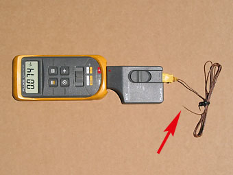 � Thermocouples are tough, and have very little mass. � They're smaller than the thin cable that goes to them! � (In this photo the multimeter is reading 74° F.) | �
� | 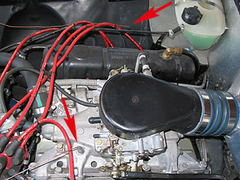 � I positioned two thermocouples, as shown here. � One is actually INSIDE manifold runner number "1". � (The cowl-induction system is shown installed.) | �
� The initial temperature measurements below were made in Longmont Colorado on two � mornings in March. Ambient temperature was about 64° F on both days, � and humidity was very low. (The NOAA website reported dew point was 28° F.) � Our elevation is in the ballpark of 5100 feet above sea level. Due to differences � in conditions, your results would probably vary. For further details about the � test vehicle, please see below.�
� The initial test procedure was pretty simple (if arbitrary)... the "cold" engine � was started and allowed to idle normally. Temperature readings were recorded � at thirty second intervals for thirty minutes - long enough for everything to � reach steady-state temperatures. Since the electric cooling fans are manually � operated on my car, I turned them on when the coolant temperature gauge read "190". �
� For the first morning's test the cowl induction system was intact. For the second � morning's test I removed the blue hose, so air was drawn from the engine compartment, � and I blocked off the air filter aperture in the firewall. �
�
�
� This chart also shows that the temperature of the air/fuel mixture (aka "charge air") � inside the intake manifold runner can be significantly and reliably lower on a car � with cold air induction. From the nine-minute mark onward, the charge air � presented for combustion was consistently about 18° F cooler when cold air � induction was fitted. Depending on your perspective, the temperature differences � may be more or less than expected. �
� We clearly demonstrated something important: "Colder air in" results in "colder air out". �
� Considering that under-hood air temperature rose to over 150° F (i.e. 86° � over ambient), I expected to see a bigger difference between the two charge air � temperature curves. At the end of the first morning's test, air was rising from � 64° F to 190° F within the induction tract - an increase of 126°. � At the end of the second day's test, air was only rising from 160° F to � 212° F - an increase of only 52°! �
� MGB V6 builder Scot Abbott provided some explanation: "The cooler air will � not so readily vaporize the fuel and hence will be cooled less by evaporation � than the warmer air, which will evaporate the fuel more readily and hence be � cooled more in the process. This would cause a leveling of the temperatures � of the differing temperature air masses."�
� Disappointing. By this time, I was starting to wish this article had been about air dams.�
� I decided to take a drive on rural roads east of town. �
� I actually ended up taking two drives to road test the same two induction � configurations as before. Each drive was about 30 minutes long and included rural � roads with speeds up to 60 MPH and occasional stop-signs and traffic lights. �
� My first observation was that engine compartment air temperature drops steadily � when the car is moving, and rises quickly when the car is stopped, within � predictable limits. During the two test drives I never saw the engine compartment � air temperature go below 90° or above 210°. On average it was about � halfway in between. (Notice that the sensor was located at valve cover height but � above the exhaust headers. This location was chosen because it's approximately � where a round drop-base air cleaner or Holley "Hi-Tek" air cleaner would draw � air from. For road testing the sensor cables were re-routed, through the hole � behind the master cylinders, back into the cabin.)�
� Charge air temperature readings behaved more interestingly. Downstream of the � carburetor, air temperature is clearly and directly affected by fuel flow. (You� might expect higher engine RPM and resulting increased airflow would noticeably � reduce charge air temperature, but that effect is overshadowed.)�
� The first drive was with cold air (cowl) induction. Temperature swung quickly � between 90° F and over 180° F. Readings dropped like a rock during � acceleration, and rose immediately when the throttle was released. They were � much more steady at cruise, typically between 120° and 150°, although � they varied with speed and engine load. At stoplights, charge air temperature � went to about 170° or 175°, and then crept slowly upward toward 190°. �
� The second test drive, with cold air induction disconnected, was more surprising. � Even though engine compartment air temperature was sometimes quite moderate, � and even though I tried all sorts of acceleration rates and throttle positions, � in this drive I never once saw the charge air temperature go below 128° F. �
� Temperatures observed during the two drives are summarized in the following table:�
�
| Temperature Inside Intake Runner | ||
| Full Range Observed | ||
| Cruise (approximate) | ||
| Idle (stabilized) | ||
| Wide Open Throttle (best observed) | ||
� Bottom line? The MGB cold air (cowl) induction system reduced the temperature of the � air/fuel mixture (measured about halfway between carburetor jets and intake valves) in � all tested situations, summarized as follows:�
�
| Test 1 | stationary steady-state operation (like when you're waiting at a long stoplight) | |||
| Test 2 | accelerating at wide-open-throttle (like when you're racing to the next stoplight) | |||
� �
Calculation of Cold Air Induction Performance Benefits
� What do all these ramblings and numbers mean? Pragmatically, we're just looking for a � realistic estimate for expected power gain from the charge air temperature � reductions we actually observed. To that end, my suggestion is to return to SAE J1349 � and to the correction factor it prescribes for dynamometer calibration. �� Even though SAE J1349 was developed for comparing temperatures UPSTREAM of the induction � system - substituting the wide-open-throttle temperatures we observed INSIDE the number � "1" intake runner is instructive if only because it provides a very "conservative" � system performance estimate to contrast against the preliminary numbers we started � with (above). �
� You can use Richard Shelquist's nifty calculator... or just go straight to the SAE J1349 correction formula:�
� hp2 = hp1 * [1.18 * (T2a/T1a)0.5 - 0.18]
� where: hp2 = the new horsepower at temperature T2a
� hp1 = the old horsepower at temperature T1a
� T1a = the absolute temperature of the fuel / air mixture provided by cold-air induction
� T2a = the absolute temperature of the fuel / air mixture provided by conventional induction
�
� When accelerating at wide-open-throttle: �
� T2a = 587° R�
� T1a = 550° R�
� 1.18 * (T2a / T1a)0.5 - 0.18 = 1.18 * (587° R / 550° R)0.5 - 0.18 = 1.038�
� This quick calculation, based on actual measurements on a typical spring day, � indicates that cold air induction on my V8-powered MGB should be providing � at least 3.8 percent power increase at wide open throttle. �
� Cold air induction systems provide their maximum performance advantage after � leaving a stop, when engine compartment air is relatively high, and when the � vehicle is accelerating at wide-open-throttle. �
� In combination with ram-air effect at high speeds (e.g. at the dragstrip) the � potential performance benefit may temporarily be higher. (Add the 0.47 percent � "boost effect" estimated above to the 3.8 percent estimated here.) �
� On a car like Kelly Stevenson's Ford 5.0, fuel-injected, V8-powered MGB (shown above), � a 4.3 percent gain translates to over eleven horsepower. That's a lot of benefit � from simply fitting a straight, foot-long aluminum tube!�
� It would be wild over-selling to call cold air induction a "poor man's supercharger"� based on the benefits we observed, but the benefits are real and they are significant. � We'd be hard-pressed to identify a cheaper, easier, or lower-risk way to improve � engine performance.�
� There will be some readers who won't believe the benefits of cold air � induction until they see dynamometer results. To them I'd point out that � a typical dynamometer installation would have difficulty modeling how � temperature changes under the hood as a vehicle moves through air. It would � be best to more fully instrument a car and do additional road testing. � Perhaps we'll be able to revisit the question in the future with a proper� (continuously monitoring) data acquisition system.�
� To be fair, it shouldn't be forgotten that efficiently venting heat out of the � engine compartment would reduce the relative advantage of cold air induction.�
� The cold air induction system itself seems to provide a modest benefit to � engine cooling. In our stationary tests we found that engine compartment air � temperature was consistently about six degrees lower with cold air induction � operating. Once up to operating temperature, the engine should operate slightly � more efficiently. On the other hand, the engine's rise to operating temperature � will be slower, which is undesirable from an engine wear, fuel economy, or air � pollution point of view. �
� Larry Shimp suggested a potential way to increase the benefit of cold air � induction further:
"One other interesting possibility with a cold air intake � is that if it is in the form of a long tube to the front of the car, and the � tube isn't too big in diameter, it could be refined into an intake tuning device. � It would have a natural resonant frequency (like a tuned exhaust) of relatively � low frequency, and if properly tuned it might help low speed torque."�
�
� Quite a few people believe that cooler air flowing through a carburetor doesn't � automatically drag more fuel into the intake, and therefore they assume that � cold air induction must make carbureted engines harder to tune for maximum power.� The fundamental belief is wrong, and so is the associated conclusion.�
� Although carburetors don't have a "brain" or sensor to measure temperature, all � carburetors function similarly in that pressure drop across a venturi is the � mechanism that pulls fuel into the venturi. The pressure drop itself is a function � of air density. Temperature and ram air effect both play into that equation. In � other words, carburetors are largely self-adapting. �
� Carburetors are surprisingly effective at adapting within the limited range of � operating conditions we subject them to. Without cold air induction, your carburetor � must accommodate a significantly wider range of air temperatures than if you supplied � air from outside the engine compartment. In other words, the term "cold air induction" � is misleading; we're really talking about "less preheated induction"! (Still � skeptical? If you start your engine on a freezing-cold day and allow it to warm up, � the temperature inside the engine compartment rises from about 32° to at least � 100°, and probably higher. On a 100° day your engine compartment starts at � 100° and rises to over 160°. Obviously outside air doesn't vary 130°, � even with global warming. With cold air induction, your car sees a narrower range of � air temperatures both season-to-season and minute-to-minute.) On modified British � sports cars, cold air induction generally simplifies carburetor tuning and � reduces common carburetor maladies such as "boiling" or percolation. �
� Larry Shimp added the following insights: �
� "In general, for a port fuel injected engine, the colder the air the better. Fuel � goes almost directly into the cylinders. But for an engine with a carburetor, � (especially a central carburetor as opposed to one barrel per cylinder Weber � carburetors) the fuel must stay in the air stream all the way to the cylinders, � and so a certain amount of manifold heat is needed for economy and drivability..." � [Larry also pointed out that exhaust-heated intake manifolds can aid throttle � response, and particularly enhance the functionality of carburetors that use � accelerator pumps (which don't fully atomize the fuel they add). - editor]
� Larry continued: �
� "In the early days of emissions controls, auto manufacturers found that they had � to keep the intake air to the carburetor at as constant a temperature as possible. � They did this by thermally controlled air valves on tubing off of the air cleaner. � One tube went to a cold air intake in the front of the car, the other to a spot � just above the exhaust manifold. The air valve mixed the cold and hot air to give � a reasonably constant intake temperature. With this, they were able to use leaner � mixtures without throttle response problems.�
� "Carburetor icing can be a serious problem with a cold air intake. This condition � occurs under high humidity conditions when the air temperature is between about � 32° and 40° F. Evaporation of the fuel in the carburetor will cool the air � to below freezing, and the water vapor in the air will condense out and freeze in � the carburetor, blocking jets or even jamming the throttle. In Colorado, there is � almost never enough humidity to cause this, but it is a real problem in other � places."�
� If you do a lot of cold weather driving, cold air induction may not be a good � fit for you. But frankly I believe most V6 and V8 MGB conversions see decreased� usage as weather approaches or crosses the freezing mark. I've used cold air induction � on my V8 conversion since 1992. From my point of view the system has performed � very well. Your expectations and results may vary.�
� If your engine is equipped with electronic fuel injection, cold air induction � is a "no-brainer"! Your engine's control system is already equipped to automatically � adjust to and benefit from cooler air when it's available. Furthermore, it's typically � easier and cheaper to fabricate (or purchase) simple tubing or ductwork to provide � cool air to fuel-injected engines.�
� The newest "electronic" engines can benefit even more from ram-air and cold air � induction because they automatically fine tune ignition timing based on air � density, as typically measured by a MAF sensor. Cooler intake air means ignition � timing can be advanced slightly more, because tendency for potentially damaging � preignition ("pinging") is reduced.�
� If your car tends to "ping" when driven on hot days, installing cold air induction � may help. Furthermore, if a car with conventional ignition is converted to cold air � intake, it might be a good idea to see if a little more timing advance can be used - � to realize even more performance improvement! � �
� The car has an air dam, and it rides on low profile 14" tires. The original grille and � oil cooler have been removed. The radiator core is stock MGB (although the mounting is � modified). Before testing, I added foam rubber between the top of the radiator and the � hood to block air from bypassing the radiator. Stock MGBs have a seal at the radiator � bulkhead and also a seal around the rear of the hood. My inner fenders are stock. I � haven't fitted RV8-style headers, which would alter the test results due to the holes they � require in the inner fenders. �
� Before starting any testing, I filled the fuel tank with "Premium Unleaded", and I � didn't top it off again. No changes whatsoever were made to carburetor or ignition � tuning throughout the tests. The carburetor choke plate on my carburetor was removed � years ago, and the throttle linkage doesn't have a fast idle setting. Due to differences � between our vehicles, your results would probably vary.�
�
� Disclaimer: This page was researched and compiled by Curtis Jacobson. Views expressed � are those of the author, and are provided without warrantee or guarantee. Apply at your � own risk.�
� Photos by Curtis Jacobson (except the first photo, which was by Bob Elwin, and the photos of Jim Strait's and Kelly Stevenson's cars, which were provided by the owners). All rights reserved.�
�
�
What About Stoichiometry?
� In theory, a "stoich" mixture has just enough oxygen for complete combustion � of the available fuel. Basic stoichiometry tells us that in order to produce � more power, we need to maintain the correct air/fuel ratio. How do ram-air � effect and cold air induction effect stoichiometry? I was surprised to learn � that the answers to this question are pretty similar for both carbureted and � electronically fuel injected engines. �� Quite a few people believe that cooler air flowing through a carburetor doesn't � automatically drag more fuel into the intake, and therefore they assume that � cold air induction must make carbureted engines harder to tune for maximum power.� The fundamental belief is wrong, and so is the associated conclusion.�
� Although carburetors don't have a "brain" or sensor to measure temperature, all � carburetors function similarly in that pressure drop across a venturi is the � mechanism that pulls fuel into the venturi. The pressure drop itself is a function � of air density. Temperature and ram air effect both play into that equation. In � other words, carburetors are largely self-adapting. �
� Carburetors are surprisingly effective at adapting within the limited range of � operating conditions we subject them to. Without cold air induction, your carburetor � must accommodate a significantly wider range of air temperatures than if you supplied � air from outside the engine compartment. In other words, the term "cold air induction" � is misleading; we're really talking about "less preheated induction"! (Still � skeptical? If you start your engine on a freezing-cold day and allow it to warm up, � the temperature inside the engine compartment rises from about 32° to at least � 100°, and probably higher. On a 100° day your engine compartment starts at � 100° and rises to over 160°. Obviously outside air doesn't vary 130°, � even with global warming. With cold air induction, your car sees a narrower range of � air temperatures both season-to-season and minute-to-minute.) On modified British � sports cars, cold air induction generally simplifies carburetor tuning and � reduces common carburetor maladies such as "boiling" or percolation. �
� Larry Shimp added the following insights: �
� "In general, for a port fuel injected engine, the colder the air the better. Fuel � goes almost directly into the cylinders. But for an engine with a carburetor, � (especially a central carburetor as opposed to one barrel per cylinder Weber � carburetors) the fuel must stay in the air stream all the way to the cylinders, � and so a certain amount of manifold heat is needed for economy and drivability..." � [Larry also pointed out that exhaust-heated intake manifolds can aid throttle � response, and particularly enhance the functionality of carburetors that use � accelerator pumps (which don't fully atomize the fuel they add). - editor]
� Larry continued: �
� "In the early days of emissions controls, auto manufacturers found that they had � to keep the intake air to the carburetor at as constant a temperature as possible. � They did this by thermally controlled air valves on tubing off of the air cleaner. � One tube went to a cold air intake in the front of the car, the other to a spot � just above the exhaust manifold. The air valve mixed the cold and hot air to give � a reasonably constant intake temperature. With this, they were able to use leaner � mixtures without throttle response problems.�
� "Carburetor icing can be a serious problem with a cold air intake. This condition � occurs under high humidity conditions when the air temperature is between about � 32° and 40° F. Evaporation of the fuel in the carburetor will cool the air � to below freezing, and the water vapor in the air will condense out and freeze in � the carburetor, blocking jets or even jamming the throttle. In Colorado, there is � almost never enough humidity to cause this, but it is a real problem in other � places."�
� If you do a lot of cold weather driving, cold air induction may not be a good � fit for you. But frankly I believe most V6 and V8 MGB conversions see decreased� usage as weather approaches or crosses the freezing mark. I've used cold air induction � on my V8 conversion since 1992. From my point of view the system has performed � very well. Your expectations and results may vary.�
� If your engine is equipped with electronic fuel injection, cold air induction � is a "no-brainer"! Your engine's control system is already equipped to automatically � adjust to and benefit from cooler air when it's available. Furthermore, it's typically � easier and cheaper to fabricate (or purchase) simple tubing or ductwork to provide � cool air to fuel-injected engines.�
� The newest "electronic" engines can benefit even more from ram-air and cold air � induction because they automatically fine tune ignition timing based on air � density, as typically measured by a MAF sensor. Cooler intake air means ignition � timing can be advanced slightly more, because tendency for potentially damaging � preignition ("pinging") is reduced.�
� If your car tends to "ping" when driven on hot days, installing cold air induction � may help. Furthermore, if a car with conventional ignition is converted to cold air � intake, it might be a good idea to see if a little more timing advance can be used - � to realize even more performance improvement! � �
The Test Vehicle
� My 1971 MGB-GT "test vehicle"� is fitted with a fairly mildly tuned Buick 215 V8 engine. For people who aren't familiar � with the Buick 215, it's an all-aluminum engine where the aluminum intake manifold is � not heated by any exhaust passage and the manifold is also entirely unconnected to the � engine block. (The lifter gallery is covered by a "valley pan" which also serves as a � gasket between the manifold and the cylinder heads.) My engine breathes through an � Edelbrock 1404 four-barrel downdraft carburetor and a panel air filter (mounted flush � to the firewall). �� The car has an air dam, and it rides on low profile 14" tires. The original grille and � oil cooler have been removed. The radiator core is stock MGB (although the mounting is � modified). Before testing, I added foam rubber between the top of the radiator and the � hood to block air from bypassing the radiator. Stock MGBs have a seal at the radiator � bulkhead and also a seal around the rear of the hood. My inner fenders are stock. I � haven't fitted RV8-style headers, which would alter the test results due to the holes they � require in the inner fenders. �
� Before starting any testing, I filled the fuel tank with "Premium Unleaded", and I � didn't top it off again. No changes whatsoever were made to carburetor or ignition � tuning throughout the tests. The carburetor choke plate on my carburetor was removed � years ago, and the throttle linkage doesn't have a fast idle setting. Due to differences � between our vehicles, your results would probably vary.�
�
A Word of Thanks
� This article wouldn't have come together without very generous contributions from three � newsletter readers. I wish to thank Steve DeGroat of Lugoff SC, David Maples of Augusta � GA, and George Cooper of Weeki Wachee FL. Their financial contributions paid for the new � measurement tools I used in researching this article. If you think this article was � too damn long, blame Larry Shimp. Larry's encouragement and thought provoking comments � encouraged me to extend the article in several areas.� �� Disclaimer: This page was researched and compiled by Curtis Jacobson. Views expressed � are those of the author, and are provided without warrantee or guarantee. Apply at your � own risk.�
� Photos by Curtis Jacobson (except the first photo, which was by Bob Elwin, and the photos of Jim Strait's and Kelly Stevenson's cars, which were provided by the owners). All rights reserved.�