
�

�
"Measuring a Summer Day" �
1971 MGB/GT with Buick 215cid V8 (owner: Curtis Jacobson)�
Cooling System Design Considerations
� as published in British V8 Newsletter, Volume XIV Issue 2, August 2006�� by: Curtis Jacobson�
� The components we think of collectively as "the cooling system" are responsible for regulating � engine temperature within a prescribed range (e.g. 185 to 205 degrees Fahrenheit). Besides simply � cooling, this system must help the engine come up to temperature quickly and evenly. Especially in � cool weather, it's important the cooling system not over-perform because cold engines wear rapidly, � pollute more, achieve inferior fuel economy, and typically produce less power. Perhaps more � people are familiar with the other performance extreme. Under-performing systems are prone to � catastrophic failures such as burst hoses and warped metal under angry storm clouds of superheated � steam. Engines that run cool cause uncomfortable passengers in cool weather, whereas engines that � run hot cause discomfort on warm days. But for maximum performance (particularly on carbureted � engines) achieving a very consistent operating temperature is extremely helpful for fine tuning � overall engine performance.
�
�
�
� There are two primary factors to consider: air flow and heat transfer.� �
Air Flow:
� � Air moving through the engine compartment, but not through the radiator, � provides very inefficient cooling. To ensure all incoming air goes through the radiator, � recirculation shields around the radiator are called for. They don't have to be totally � air-tight, but every bit of air that slips around the radiator is lost-potential.�
� By the same reasoning, it's an excellent idea to place a shroud and/or "fan ring" around � cooling fans. An engine cooling fan's purpose is to move a current of air, not to simply � "stir up" the air. Unlike paint being stirred in a can, the air moving past a cooling fan� should come past the blades only exactly once.
�
� Fan shrouds duct the air that passes through the radiator core down to the circular � cross-section of the fan or fans. With a shroud fitted, the fans can draw air through � the entire area covered by the shroud, and potentially through every square inch of � radiator core. Fan shrouds are particularly helpful when the vehicle is stationary. At � high road speed, in installations with a lot of natural airflow through the radiator, � fan shrouds can sometimes restrict airflow significantly. Many car manufacturers install � rubber flaps on their fan shrouds that act as valves. Air pressure forces the flaps � open at road speed, so air bypasses the fan(s).
�
�
| �
Enjoying this article? Our magazine is funded through the generous support of readers like you! � To contribute to our operating budget, please click here and follow the instructions. � (Suggested contribution is twenty bucks per year. Feel free to give more!)� |
� Fans work most efficiently when fitted with fan rings. A fan ring is essentially a very short � bit of ductwork (either separated from the tips by a small air gap and stationary, or � less-commonly integrally attached to the propeller tips and rotating with them). Fan rings � provide a straight and efficient current of air by restricting vortexes and turbulence at � the blade tips.
�
� Fan rings can be used in conjunction with fan shrouds, but in some installations it makes � sense to use them on their own! Three factors that suggest use of fan rings without shrouds � are: 1. the vehicle will mainly be traveling at high speed, 2. the fan's cross-sectional � area is a relatively large fraction of radiator-core area, and/or 3. for whatever reason, the � fans are mounted in front of the radiator where a shroud is usually too obstructive. When a fan � ring is fitted without a shroud, it should extend right up close to the radiator fins.
�
� Fan shrouds and rings have the additional safety benefit of helping to keep fingers intact.
�
� What about the fan itself? There are many fan-related design decisions, including engine-driven � versus electric, and diameter. The amount of room available is often a driving factor in these � decisions. As some engine driven fans have been shown to provide insufficient airflow at idle, � it has become more common to supplement them with one or more electric fans.
�
� Engine driven fans waste power and fuel by spinning when not needed, when the engine is � below temperature and also at speed when ram-air makes them redundant. "Flex" fans are � designed to address the later issue by moving proportionally less air per revolution at � high RPM. Clutch devices for engine-driven fans are uncommon on sports cars.
�
� Many installers elect to omit the engine-driven fan in lieu of one or more electrically � driven fan. One advantage of this decision is that it's easier to achieve close fit � between the propeller tips and fan shroud or fan ring. (No extra room is required to � accommodate engine rocking on the motor mounts, which incidentally are rubber on street cars � for a reason. Volvo trucks have a brilliant solution: their fan ring is mounted to the � engine and connected to the fan shroud only by a rubber grommet.)
�
�
�
� The CFM ratings on aftermarket fans should be read with great skepticism. If you can, buy � and try several fans. Return the ones you don't like.
�
� Electrical fans require a fair amount of electric current. Make sure wiring to the fans is � of sufficient gauge (i.e. cross-sectional area) and consider switching the fans on and off � with a relay because relays are designed to handle more current than typical toggle or � thermostatic switches. Any voltage drop that occurs because of resistance in your wiring or � switches will reduce fan motor speed. Finally, remember to observe polarity. The fan won't � work so great if it's spinning backwards!
�
� Air flow obstructions can also significantly reduce cooling system performance. If anything � is blocking airflow into or out of the radiator core, look for ways to remove or relocate � it. (Throwing away your car's cosmetic grille will give it that racecar look!) It is prudent, � of course, to provide some sort of protection to keep debris out of the fans and radiator.
�
� Air flowing into the engine compartment should have a clear path to flow out, or air � pressure will build in the engine compartment and reduce airflow through the radiator.
�
� When a vehicle is in motion there will always be areas of higher and lower air pressure � around and within it. It makes good sense to use this fact to advantage. For example, the � cowl area (outside and at the base of the windshield) is a high pressure area, which is why � cowl fresh-air vents work so well. When it comes to engine cooling, it should be noted � that (at road speed) the front wheel area is typically lower pressure than the engine � compartment. Holes cut in the inner fender-wings typically draw hot air out of the engine � compartment. (If one routes exhaust headers through the holes, they serve double-duty; � they get exhaust heat out of the engine compartment by a very direct route. MGB-V8s fitted � with "RV8-style" through-the-fender headers rarely have cooling problems.)� �
�
�
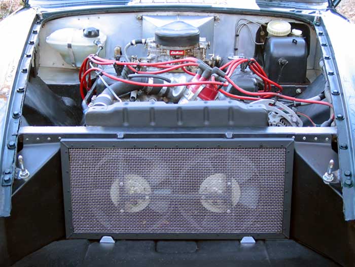
1971 MGB/GT with Buick 215cid V8 (owner: Curtis Jacobson)�
�
Figure 1:
�
• "Stock" MGB radiator (with oversized ports installed, altered mounting, and plugged cap.)
�
• Twin Honda Civic a/c condenser fans ("pushing") fitted with steel fan-rings
�
• Engine-driven fan omitted
�
• Simple mesh screen in lieu of original 1971 MGB grille
�
• Volkswagen Jetta pressure tank (aka "header tank")
�
• Plumbing as described in the text below
�
• Stock 1963 Buick water pump, with stock pulleys
�
• Oil cooler omitted (note: Buick V6 "metric" oil pump is used with directly-mounted spin-on filter.)
�
• Air damn fitted below bumper ("urethane" type with no air holes)
�
• Stock (un-louvered) MGB hood (removed for photograph)
�
• Un-vented inner-fender wings (i.e. headers exit the conventional route...)
�
• Heater omitted, and home-made "cowl-induction" system fitted in its place
�
• Note: In fifteen years of operation (in North Carolina and in Colorado) this cooling system has never over-heated.
�
HEAT TRANSFER:
� � Here's a tip that may save you a lot of money. You probably don't actually need a custom-made � radiator! For example, many people have found that the standard MGB radiator core is more � than adequate for a 200+ horsepower V8 engine, provided the overall cooling system is � well conceived and in good maintenance. It's relatively easy to modify old-fashioned OEM radiators � to get the port sizes and locations you need. Old radiators do get clogged up, but your local � radiator shop can unclog them, or you can buy a standard replacement radiator for most models � of British cars (and typically they're cheaper than custom-made radiators.)�
� Your local radiator shop can also re-core your old radiator, and doing so is often economical. If � space permits in you application, you might ask them about installing a thicker or longer core. � Adding a couple extra inches between top and bottom tanks is generally better, for reasons explained � below. An "MGB V8 radiator", as sold in some parts catalogs, is an MGB radiator with an extra long � core.
�
� It certainly doesn't hurt to have a radiator with extra capacity, provided you use it wisely. � If you decide to go shopping for a radiator, whether from a different model car (e.g. 1965 Ford � Falcon radiators are particularly popular on MGB conversions) or from a custom radiator manufacturer, � here are some things to consider:
�
� Copper is a slightly more efficient material for radiator cores than aluminum, although the difference � is less than many people think. Many people also report that copper-and-brass radiators last longer � before cracking/leaking. There are, however, many design parameters at play (e.g. tube size and � wall-thickness, variation in solder, etc.) and we don't have access to any reliable numbers to � quantify or prove either of these statements in practice.
�
� Copper and brass radiators are certainly much easier to modify or repair than aluminum (because � soldering is much easier than TIG welding.)
�
� Aluminum is lighter weight than copper or brass. Due to location, extra pounds of radiator (and � coolant) will affect the car's weight bias more than extra pounds of engine.
�
� As a matter of common sense, thicker radiators can provide more heat transfer than thinner radiators,� provided they aren't so thick that they restrict airflow. Re-coring three-row radiators with thicker � four-row cores is commonly done, but the added row will not be as efficient as the first three. � Air flowing through the last row will have been heated by the first three, so heat exchange � (from coolant to air) will not be as great for these rows. For this reason, if room allows, a larger � core area may be much more beneficial than a thicker core.
�
� If you have occasion to visually compare two radiator cores, look at how the fins contact the tubes. � Older-style tube-and-fin construction, where the tubes pass through holes in the fins, are generally � less efficient than newer-style serpentine fins. On tube-and-fin radiators, there is a lot of variation � in fin design and on how tightly the fins contact the tubes. A tight mechanical connection between � tubes and fins is very desirable because it facilitates efficient heat transfer into the fins.
�
� Radiator shops like to paint radiators black. They shouldn't. Paint reduces the efficiency of radiator � cores. (Typically aluminum radiators are anodized, instead of painted, which is a good thing.) If you � do paint your radiator, apply as thin a coat of paint as you can. Color choice won't noticeably affect � performance. (If you have an optical pyrometer this is easy enough to prove to yourself.)
�
� Interesting trivia: the total surface area of fins and tubes on a high performance radiator is � typically well over 100 times the frontal area of the radiator.
�
� Since there needs to be a pressure-relief valve somewhere in the cooling system, a remote "pressure � tank" (aka: header tank) is commonly fitted. Although metal pressure tanks are popular, they � aren't recommended. Provided it's mounted as the highest point in the cooling system, a strong, � transparent, relatively high-volume, plastic pressure tank of the kind found on many newer � European cars makes it possible to verify coolant level at a glance and to see if contaminants � are in the system. Junk yards give these tanks away for free, or you can buy them economically � at the VW parts counter. You'll know you're buying a pressure tank because a relief valve will � be mounted in the cap, and the cap will be labeled with its pressure-rating. These tanks normally � have two ports: a smaller one at the top and a larger one at the bottom. A hose (or preferably � rigid tubing) should travel uphill all the way from the top tank of your radiator to the pressure � tank. A second, larger hose (or preferably rigid pipe) is highly recommended from the inlet � port on your water pump uphill to the pressure tank. (See photo above for illustration of these � recommendations. Please note that second pipe mentioned is part of a strategy to reduce cavitation � at the pump, which is discussed below.)
�
� Air trapped within the cooling system severely compromises its performance. For filling coolant� and purging air, there needs to be a vent at the highest point in the system. It's common to � see a bung (with threaded plug) soldered to the radiator top tank for this purpose, but if the � pressure tank is mounted high enough and the radiator top tank is vented to the pressure tank � (as previously suggested), a bleed plug on the radiator isn't necessary.
�
� In practice, the pressure relief valve itself really should be the "vent" at the highest point � in the cooling system. If the pressure relief valve is lower in the system, there's little hope � for it releasing air without releasing coolant too. Ideally coolant flow should be relatively � still in close proximity to the pressure relief valve so air bubbles will accumulate (and not be � swept away.) When the pressure relief valve is in contact with flowing water, it is far more � likely to open at a lower-than-intended system pressure (i.e. open due to a "local pressure spike").
�
� Big problems are likely if the highest point in the cooling system is within the engine itself. � This problem may sometimes be avoided by fitting the remote pressure tank high on the firewall. � Don't forget that the heater is part of the cooling system too, and that it may also need to be � purged of air.
�
� Make sure all water hoses throughout the cooling system are routed so that they won't become � crushed or kinked. Formed metal piping, joined with short lengths of Gates green-stripe hose, � is really the hot ticket. The coolant ports on your intake manifold and water pump define what � hose diameters you should be using. Your local radiator shop can quickly and easily replace � the input and outlet ports on your radiator with larger diameter ports (salvaged from an old � radiator.)
�
� Make sure your engine thermostat opens fully. (You can test it by putting it in a sauce � pan of water on your kitchen stove.) If you have a candy thermometer you can verify that it � opens at the rated temperature.
�
� Use high quality coolant, mixed 50/50 with water. High quality coolant already contains a � generous cocktail of "water wetters" and corrosion inhibitors, so additional additives aren't � recommended. Propylene glycol is better for the environment than ethylene glycol, and you should � use it. (Besides being something you don't want in your local groundwater, ethylene glycol � apparently tastes good to animals. It causes kidney failure and painful death. Propylene glycol � is relatively inert. It's an ingredient in many foods, including Cool Whip.) Neither kind should � go down your drain; take used coolant to a recycling center. Don't mix the two kinds because � they have two different specific gravities, so you won't be able to reliably verify coolant � concentration by measuring specific gravity. As for the water itself, distilled water is � generally recommended over tap water to further prevent ionization that could result in � corrosion and pitting of aluminum components.
�
� It has come to our attention that some aftermarket parts suppliers categorically recommend over-speeding � factory water pumps by 30 to 35 percent by fitting aftermarket pulleys with non-OEM ratios. In our � opinion, that may be very bad advice for British V8 readers. It's certainly bad advice for many high � performance (e.g. road or endurance racing) applications. Our advice is to maintain the OEM pulley � ratio. If you feel compelled to tinker with pulley ratio, we advise that production-car engines � which are routinely operated at high RPM should generally slow down coolant flow. For one thing, � water pumps are prone to cavitate when operated at too high speed.
�
� When a pump cavitates, it spins without pushing water, which creates vapor bubbles. A more generic � explanation is that cavitation tends to occur when a pressure-drop and a temperature-rise occur � simultaneously. Cavitation most frequently occurs right at the water pump. Vapor bubbles that are � pressurized as they pass through the pump, collapse or implode with destructive force. The superheated � steam bubbles created by cavitation can cause severe damage throughout the cooling system, including � especially aluminum heads and radiators. (Incidentally, modern water pump impeller profiles are � engineered to help reduce cavitation. Those of us that choose to use forty year old water pumps are � more vulnerable.) If in doubt about your application, leave your pulleys at the factory-designed ratio.
�
� In an article in April 2004's Motor Age magazine, Kevin McCartney provides a further warning: � "High-performance water pumps often increase cavitation. The damage may show up in the intake manifold � or elsewhere instead of the pump itself. Standard water pumps provide all the flow required for proper � engine cooling. A wide-open thermostat actually restricts coolant flow below the capacity of a standard � water pump. So a pump designed to increase capacity will usually increase pressure changes and cavitation, � while doing very little to actually increase flow unless the thermostat is removed. Of course, this is � not recommended, as removing the thermostat will cause other problems."
�
�
�
� What about secondary heat exchangers? Oil coolers are a traditional option. If you're fitting a � BOP/R engine in an MGB, consider omitting the oil cooler because it's not needed and it introduces � problems of its own. These engines are happy to have all the oil flow they can get, and the oil � cooler can significantly reduce flow. (It's desirable that cold engines come up to temperature � quickly, so the oil cooler should have a thermostatic valve, but thermostats and valves add their � own respective failure modes.) Hoses are expensive, and they're a pain to route. Modern motor oil � formulations are much more resistant to breakdown from heat than the motor oils of the 1960's, so � "sludge" isn't the issue it used to be. If you feel you must mount an oil cooler, put it someplace � where it doesn't obstruct airflow to the radiator, where it gets enough airflow to work, and where � it's protected from curbs and road debris.
�
� Although engine tuning is outside the scope of this article, we'd be remiss not to mention that � engine tuning problems very frequently cause cooling problems! If you have a cooling problem, � consider checking that your ignition's vacuum advance is functioning properly. The manifold vacuum � advance system is an important aid to idle and low speed cooling. Secondly, verify your air/fuel � mixture. Lean carburetor jetting will cause an engine to run hot. Troubleshooting this can be complex � because carburetors have different jetting at idle and cruise speeds. A jetting error should especially � be suspected in any car that runs cool at low engine speeds, but runs hot at cruise speed. All these � factors are interrelated - that's part of the challenge of engineering your own car!�
� Disclaimer: This page was researched and written by Curtis Jacobson, but it was inspired by a � few paragraphs formerly included in Dan Master's essay on design considerations for those � contemplating an engine swap. Views expressed are those of the author, and are provided without � warrantee or guarantee. Apply at your own risk.�
� Photos by Curtis Jacobson. All rights reserved. �
� Note: If you like this article, you'll probably also like � "Tuning for Temperature Control" � by Jim Blackwood.
� Editor's note: � Looking for tricks and tips? Check out the � British V8 Photo Gallery to see how pretty a Ford Falcon radiator looks in Bruce Mills' 74.5 MGB, how � Martyn Harvey created a simple, effective de facto duct between the slam panel and radiator on his 1980 MGB, � how Mikel Moor notched and reinforced his frame to make room for an extra-wide cross-flow radiator, how � Dale Spooner fabricated an elegant aluminum fan shroud, how Robert Milner slipped a nifty and powerful � "side-winder" belt-driven electric fan into a very tight space, how Robert Milks bleeds air from his top hose, � how Jim Stuart used a Volvo pressure tank on his 1973 MGB-GT, how Bill Jacobson (no relation) mounted his � pressure cap very high and also fitted trick chromed-steel coolant pipes, etc., etc. There are over fifteen � hundred high-quality color photos in our gallery, so you'll find many more ideas! �