�
 �
�
�
�
�
�
�
�
�
�
�
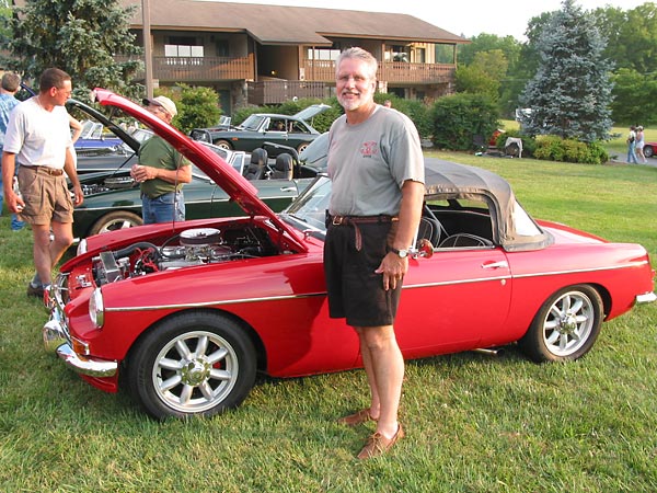
� by: Jeff Howell�
� I have thought much about wiring/rewiring the MGB as I have been left on the side of � the road on several outings with no power. I had always heard the reason the British � liked warm beer was because they all had Lucas refrigerators. The original wiring for � the MGB is mediocre at best, with all the bullet connectors and just the way the � wiring is run, it is a real pain. �
� When my car was converted to the V8, not much thought was put into the wiring, other � than running a wire across the top of the engine to the alternator and down to the � starter bolt (more on this later) and a few other modifications to get it on the road. � The Prince of Darkness hit me on one outing as I parked the car and went into a meeting � for about forty minutes. When I came out and popped into the car to start it, I thought � I smelt burnt rubber! As soon as I put the key, in I knew I was in trouble! No power, � no lights, nothing! �
�
�
�
�
 �
�
Rewiring the MGB
� as published in British V8 Newsletter, Volume XIII Issue 2, May 2005�� by: Jeff Howell�
� I have thought much about wiring/rewiring the MGB as I have been left on the side of � the road on several outings with no power. I had always heard the reason the British � liked warm beer was because they all had Lucas refrigerators. The original wiring for � the MGB is mediocre at best, with all the bullet connectors and just the way the � wiring is run, it is a real pain. �
� When my car was converted to the V8, not much thought was put into the wiring, other � than running a wire across the top of the engine to the alternator and down to the � starter bolt (more on this later) and a few other modifications to get it on the road. � The Prince of Darkness hit me on one outing as I parked the car and went into a meeting � for about forty minutes. When I came out and popped into the car to start it, I thought � I smelt burnt rubber! As soon as I put the key, in I knew I was in trouble! No power, � no lights, nothing! �
�
�
I opened the hood (bonnet) and saw that the wire running across the engine had hit a �
hot spot, burned the cover off the ten-gage wire and burn baby, burn! It burned all �
the coating off the wire, hit the starter block, and started burning into my wiring �
harness. The only thing that kept the car from burning to the ground was the connector �
burning off at the starter bolt from the heat of the burn. The wiring harness burned �
about a foot in each direction. �
� My car is a 63 "B" and it only came with two fuses from the factory. Neither fuse blew!� Well, after the tow home and looking at quite a mess, I knew there had to be a better � way.�
� I had been to one of the V8 events in Michigan and saw two different cars with no � wires in the engine bay. I really liked the look, and this became my goal. I knew � there had to be a better way than having a harness made with bad connectors and � all its wires running by very hot headers.�
��
�
� First, I pulled the entire harness out and studied the wiring diagram. What a pain! � Dan Masters had a great idea of going to Kinko's and having the diagram blown up in � size several times making it easier to read and follow the circuits. The first order � of business was to eliminate the two fuse panel under the hood (bonnet) and go with � new modern push type fuses vs. the old glass fuses. I looked at several options and � selected the Comp9 by American Auto Wire (www.americanautowire.com).� This gave me many fuses, some switched with the ignition on and some un-switched.�
� Next came the tricky part of moving all the wiring connections from the original � fuse panel in the engine bay to the passenger compartment. The goal was to eliminate � the wiring out of the engine compartment and move it to a modern fuse box. The first � thing I would suggest, beside blowing up the wiring diagram, is getting a label � device with which you type the color and wire name and print it out and loop it � over the wire(s). This will save you a lot of time later on identifying the wire(s) � and to where or what it may go within the car. �
� �
�
�
�
 �
�
�
�
�
� My car is a 63 "B" and it only came with two fuses from the factory. Neither fuse blew!� Well, after the tow home and looking at quite a mess, I knew there had to be a better � way.�
� I had been to one of the V8 events in Michigan and saw two different cars with no � wires in the engine bay. I really liked the look, and this became my goal. I knew � there had to be a better way than having a harness made with bad connectors and � all its wires running by very hot headers.�
�
| �
Enjoying this article? Our magazine is funded through the generous support of readers like you! � To contribute to our operating budget, please click here and follow the instructions. � (Suggested contribution is twenty bucks per year. Feel free to give more!)� |
� First, I pulled the entire harness out and studied the wiring diagram. What a pain! � Dan Masters had a great idea of going to Kinko's and having the diagram blown up in � size several times making it easier to read and follow the circuits. The first order � of business was to eliminate the two fuse panel under the hood (bonnet) and go with � new modern push type fuses vs. the old glass fuses. I looked at several options and � selected the Comp9 by American Auto Wire (www.americanautowire.com).� This gave me many fuses, some switched with the ignition on and some un-switched.�
� Next came the tricky part of moving all the wiring connections from the original � fuse panel in the engine bay to the passenger compartment. The goal was to eliminate � the wiring out of the engine compartment and move it to a modern fuse box. The first � thing I would suggest, beside blowing up the wiring diagram, is getting a label � device with which you type the color and wire name and print it out and loop it � over the wire(s). This will save you a lot of time later on identifying the wire(s) � and to where or what it may go within the car. �
�
�
�
�
�
�
I laid the wiring harness out on my work bench, measured the distance from where I �
wanted the connection to the new fuse box under the dash, and built the wiring �
harness from those measurements. I wanted to keep the same color scheme so I ordered �
new wire from British Wiring (http://www.britishwiring.com) after I had laid �
everything out for the front part of the wiring harness. Some of the wires I upgraded �
by one gauge to allow better current capacity.�
�
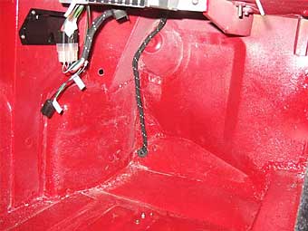
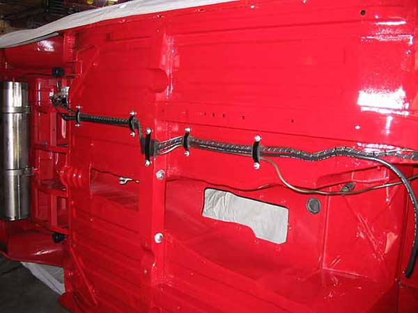
� The new harness from the Comp9 is routed through the same hole in the dash as the � original, but with a twist. Instead of the wire harness coming into the engine � compartment, I ran it through the inner fender area and cut a hole in the wheel � arch brace. This allowed me to pull the harness through the inner panel and exit � into the wheel well. I used black plastic conduit that has a split in it and used � wiring looms to hold it in place in the wheel well. I used one of the original oil � line holes in the front fender to bring the harness back into the front of the car. � I re-routed the oil lines through the fender to a remote filter attached to the � front bumper mount.�
��
 �
�
� �
�
�
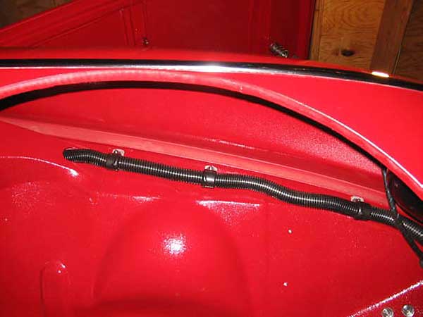
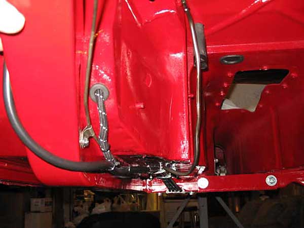
� Next was the rear harness. After much thought, I cut a half-inch hole through the � front floor panel next to the transmission tunnel to route the rear wiring harness. � I measured and ordered a new rear wiring harness from British Wiring and had them � add 48 inches to the standard length and leave the bullets off. I used the cloth � cover, as I wanted to keep the original look. If you look under the car everything � looks original, except for the route of the wire when it reaches the front of the � foot well. NO WIRES IN THE ENGINE COMPARTMENT! This was my goal and it is really clean.�
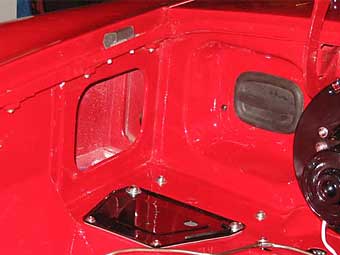
� I have decided to uses modern plastic auto wire connectors and eliminate the bullet � connectors, altogether, under the bonnet platform lock area. This will make better � connections and eliminate the mess. Other modifications included extending the wires � for the alternator and coil to route through the left side radiator support. I plan � on using looms to keep it clean and to keep wires away from hot metal. I added � another wire for the temperature sensor mounted in the radiator. This is linked � through a relay and I installed a toggle switch in the dash where the overdrive � switch was originally mounted. I can manually override the temperature sensor and � turn the fans on if desired.�
�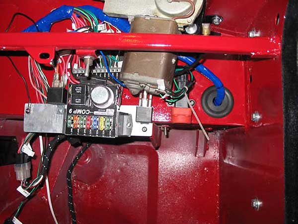
� The last issue was running power to the Comp9. I ran the hot wire from the starter � bolt to the Comp9 to supply power to the car. I will use the same hole that the � rear wiring harness comes into the passenger compartment. Make sure it is wrapped � and use a rubber grommet to keep the wires from rubbing on metal. I used ten-gauge � to bring power to the Comp9. I will use a wire wrap as a second cover just to make � sure no wire contacts metal as this is the power from the starter to the fuse panel. � You could put an in-line fuse in place, but it would need to be at least fifty amps � or greater for the entire car. I had also added the inertia switch and mounted it � next to the Comp9 and it can be seen in the pictures.�
� The other modifications include a toggle switch under the dash to kill the electric � fuel pump manually. I use this when I park the car and leave it unattended. I also � put in a small buzzer to let me know if the inertia switch has opened or if the � toggle switch is left open. This came from Radio Shack and is very quiet so it � should not be a major issue. The last modification was to add a four-way flasher. � American Auto-wire has several complete kits available on their web site. They � also sell the quick connectors that will eliminate the old unreliable bullet � connectors. Buy a very good crimping tool for the connectors such as the one sold � by British Wiring, as it is very well worth the investment. It crimps both the � insulation and the wire at the same time; very handy.�
�
�
�
�
� The new harness from the Comp9 is routed through the same hole in the dash as the � original, but with a twist. Instead of the wire harness coming into the engine � compartment, I ran it through the inner fender area and cut a hole in the wheel � arch brace. This allowed me to pull the harness through the inner panel and exit � into the wheel well. I used black plastic conduit that has a split in it and used � wiring looms to hold it in place in the wheel well. I used one of the original oil � line holes in the front fender to bring the harness back into the front of the car. � I re-routed the oil lines through the fender to a remote filter attached to the � front bumper mount.�
�
�
�
�
� Next was the rear harness. After much thought, I cut a half-inch hole through the � front floor panel next to the transmission tunnel to route the rear wiring harness. � I measured and ordered a new rear wiring harness from British Wiring and had them � add 48 inches to the standard length and leave the bullets off. I used the cloth � cover, as I wanted to keep the original look. If you look under the car everything � looks original, except for the route of the wire when it reaches the front of the � foot well. NO WIRES IN THE ENGINE COMPARTMENT! This was my goal and it is really clean.�
� I have decided to uses modern plastic auto wire connectors and eliminate the bullet � connectors, altogether, under the bonnet platform lock area. This will make better � connections and eliminate the mess. Other modifications included extending the wires � for the alternator and coil to route through the left side radiator support. I plan � on using looms to keep it clean and to keep wires away from hot metal. I added � another wire for the temperature sensor mounted in the radiator. This is linked � through a relay and I installed a toggle switch in the dash where the overdrive � switch was originally mounted. I can manually override the temperature sensor and � turn the fans on if desired.�
�
� The last issue was running power to the Comp9. I ran the hot wire from the starter � bolt to the Comp9 to supply power to the car. I will use the same hole that the � rear wiring harness comes into the passenger compartment. Make sure it is wrapped � and use a rubber grommet to keep the wires from rubbing on metal. I used ten-gauge � to bring power to the Comp9. I will use a wire wrap as a second cover just to make � sure no wire contacts metal as this is the power from the starter to the fuse panel. � You could put an in-line fuse in place, but it would need to be at least fifty amps � or greater for the entire car. I had also added the inertia switch and mounted it � next to the Comp9 and it can be seen in the pictures.�
� The other modifications include a toggle switch under the dash to kill the electric � fuel pump manually. I use this when I park the car and leave it unattended. I also � put in a small buzzer to let me know if the inertia switch has opened or if the � toggle switch is left open. This came from Radio Shack and is very quiet so it � should not be a major issue. The last modification was to add a four-way flasher. � American Auto-wire has several complete kits available on their web site. They � also sell the quick connectors that will eliminate the old unreliable bullet � connectors. Buy a very good crimping tool for the connectors such as the one sold � by British Wiring, as it is very well worth the investment. It crimps both the � insulation and the wire at the same time; very handy.�
�
�
Good luck and hopefully this will keep you rolling down the road and the lights burning.�
� James Jewell added: I was unable to find the Comp-9 on the American Autowire web-site. � I suspect it has been replaced with a newer model. Have no worries, though. American � Autowire continues to make several models of fuse/relay block. �
� The following companies market wiring kits and related products: �
��
�
� Disclaimer: This page was researched and written by Jeff Howell. Views expressed � are those of the author, and are provided without warrantee or guarantee. Apply at your � own risk.�
� Note: If you like this article, you'll probably also like � "Installing a Wiring Kit"� by Greg Myer, which appeared in Volume XIV Issue 2 of the British V8 Newsletter.�
�
�
� James Jewell added: I was unable to find the Comp-9 on the American Autowire web-site. � I suspect it has been replaced with a newer model. Have no worries, though. American � Autowire continues to make several models of fuse/relay block. �
� The following companies market wiring kits and related products: �
�
| Advance AutoWire: | www.advanceautowire.com |
| American Autowire: | www.americanautowire.com |
| Ball's Rod & Kustom: | www.ballsrodandkustom.com |
| British Wiring Inc.: | www.britishwiring.com |
| Centech Wiring: | www.centechwire.com |
| E Z Wiring Inc.: | www.ezwiring.com |
| Haywire Inc.: | www.haywireinc.com |
| Kwik Wire: | www.kwikwire.com |
| Painless Performance Products: | www.painlessperformance.com |
| Ron Francis Wiring: | www.wire-works.com |
| Watson's StreetWorks: | www.watsons-streetworks.com |
| Waytek Inc.: | www.waytekwire.com |
� Disclaimer: This page was researched and written by Jeff Howell. Views expressed � are those of the author, and are provided without warrantee or guarantee. Apply at your � own risk.�
� Note: If you like this article, you'll probably also like � "Installing a Wiring Kit"� by Greg Myer, which appeared in Volume XIV Issue 2 of the British V8 Newsletter.�