

John Hammond's 1960 Bugeye Sprite 3.4L V6
Owner: John Hammond
BritishV8 UserID: hamondale
City: Livonia, NY
Model: 1960 Bugeye Sprite
Engine: GM 3.4L V6
Conversion by: Owner
| Engine: | 2003 Chevrolet minivan 3.4L ("3400") LA1 short block, cast aluminum oil pan with cross-bolts into main bearing caps, circa 1995 cast iron heads, Comp Cams roller cam w/0.427" I/E lift and 266 degrees I/E duration, Crane 1.6:1 roller rockers, Silv-o-lite hypereutectic pistons, 9.2:1 CR, Offenhauser dual plane 4bbl manifold, Holley Sniper2 EFI, MSD 6AL-2 ignition. |
| Cooling: | Aftermarket aluminum cross flow radiator modified for radiator bottom hose placement, rear side shroud with electric puller fan, supplemental belt driven mechanical fan, hand fabricated hood shroud to duct all grill airflow through radiator. |
| Exhaust: | Custom two piece long branch headers, Flowmaster 2" mufflers, replaceable SS skid plates to mitigate low ground clearance. |
| Transmission: | BW WC T5, 3.50 1st gear, 0.73 5th gear, '95 Camaro factory OEM flywheel, clutch disc, and pressure plate, McLeod HTOB, '72 MG Midget clutch master cylinder. |
| Rear Axle: | Narrowed Ford 8" Traction-Lok, 3.80 axle ratio, Moser axles. |
| Chassis: | Subframe of 1" x 3" rectangular tubing grafted (welded) onto underside of unibody with cross member for transmission support. Additional tubing from roll bar extending forward inside rocker panels to original "jack-hole" cross member. Frame extension added for Ford 8" rear-end conversion. |
| Front Suspension: | TR-3 coil springs, Frontline tube shock conversion, heavy duty Spridget racing spindles and kingpins, reinforced OEM A-arms, heavy duty front sway bar, original rack-and-pinion steering. |
| Rear Suspension: | Custom fabricated 4-link with QA-1 coil-over-shocks. |
| Wheels/Tires: | Panasport aluminum wheels, 185-65R14 front tires, 245-50R14 rear tires. |
| Brakes: | '72 MG Midget dual master cylinder, OEM Ford 8" rear end drum brakes, Triumph Spitfire rotors/MGB caliper front brakes. |
| Electrical/Instruments: | Battery in trunk, Painless Wiring circuit breaker/fuse box, Moroso kill switch, factory original speedometer, fuel, ammeter, and oil P/temperature gauges, original cable driven tachometer converted to electronic, aftermarket vacuum and voltage gauges. See wiring schematic pdf for details. |
| Interior: | Full carpeting, custom upholstered Honda DelSol high back bucket seats. |
| Other: | Remote oil filter, custom drive shaft with front CV joint, tubbed rear wheel wells, Hurst billet shifter, Hurst "Roll Control" line lock, Speedbox speedometer cable drive, 3-point seat belts, roll bar, hideaway front license plate, exposed air cleaner, custom hood latching/lock down. |
| Weight: | Approximately 2100 lb. |
| Completed: | Initial 3.4L V6 conversion: 2000. Ford 8" rear end conversion: 2008. New 3.4L V6 and T5 transmission: 2024. Holley Sniper2 EFI: 2025 |
| Comments: | Starting off with a little history, my Dad bought this car in 1967. I think he was the third owner. He always referred to it as "The Austin," so in memory of him, that is always what I call it.
I pestered Dad to get it licensed, but it needed work right from the start. He said you fix it, you can drive it. In spite of no Brit car experience (my experience was limited to farm trucks, tractors, and machinery), I got it running well and drove it in stock condition my senior year of high school in '72. So I've had this car since I was 18 and I've grown old with it. For its age, it looks a hell of a lot better than I do. I've had it with a 948 when I was 18-21, a built 1275 when I was about 25-32, and the V6 since I turned 47 around 2001. For me, which one I prefer is not a close call.
The car's not perfect, but I think it's in nearly "final form" for me. I'd like to figure out an upgrade to the brakes and make the fiberglass hood fit better, but not much else. If I were to start the project from scratch today with what I've learned, I'd try to make the chassis mods in a way that would add less weight. If possible. Last time I weighed the car, it was 2025 lb., and that was before I swapped in the 8" Ford rear end in place of the Vega one. With the Vega rear end, fiberglass hood, battery in trunk, no heater, and me in it and a full tank of gas it was 50.4/49.6 F/R weight distribution. So it's pretty balanced and handles accordingly.
This compilation of text and pictures here is as much "what was done," rather than "how it was done," because pictures can only show so much. A lot of structure, parts, and fabrication clues are hidden behind what is visible. If you're not into the tech details, but want the story of everything that went wrong during the V6 conversion, see my post, "How It Should Not Have Been Done" over in the Pub. And some of my other Austin stories there. For the tech details, read on. Even if you get bored, be sure to scroll down to the bottom for the How It Was Done of the last photo. It's the best of the lot. |
Please support the sponsoring companies who make BritishV8 possible, including:
Chassis Modifications

A sub-frame of 1" x 3" rectangular tubing has been grafted onto the underside of the original unibody.
In the front section, it is welded to the original frame rails

The 1" x 3" tubing then branches out 45 degrees on each side, and runs back to where
it is welded to the original spring plates.

A 1" x 3" cross member is welded to the frame rails for a transmission rear mount.
1-1/2" tubing is welded to the roll bar, and runs down and inside the rocker panels on each
side, and forward, welded to the factory front cross member (where the original jack holes are).

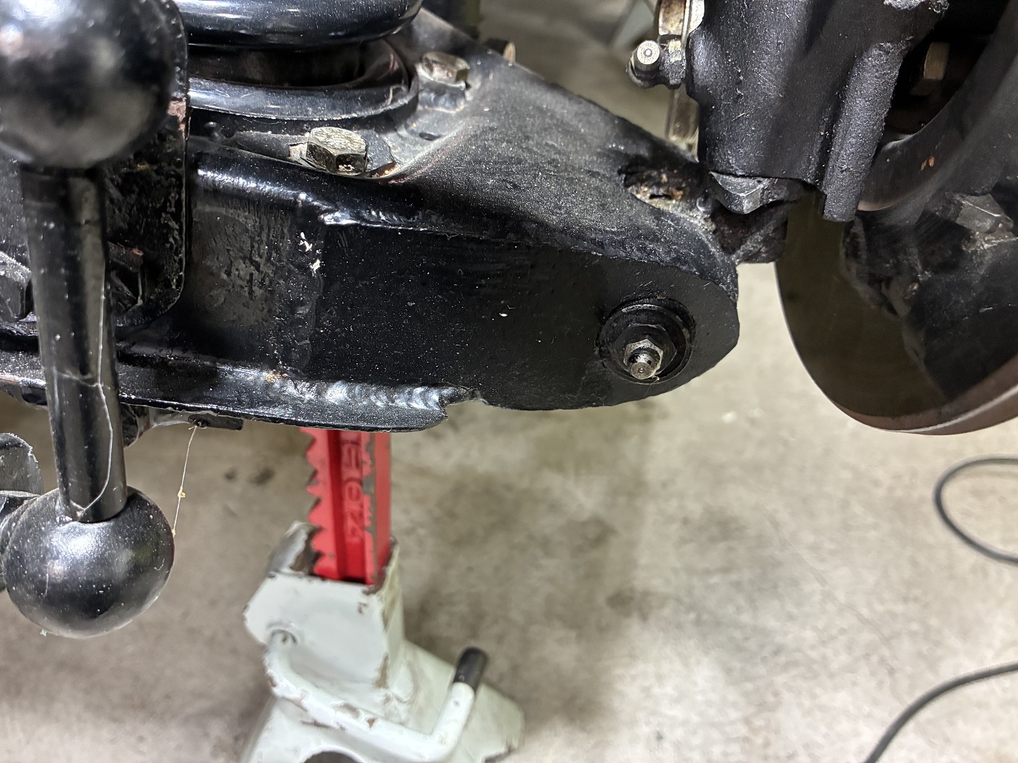
John's fabricator, who did the structural part of the 8" Ford rear end conversion, added a rear
frame extension for joining the tops of the coil-over-shocks.
Suspension Modifications

Front suspension assembly. Springs are Triumph TR-3. Sway bar is heavy duty aftermarket.
Steering is factory rack and pinion. Front spindles are heavy duty aftermarket. Tube shock
conversion is shown below.

Factory stamped steel A-arms have had additional plate welded on the underside to strengthen them to
carry the added engine weight
The outer ends of the A-arms have been reinforced at the spindle pins.
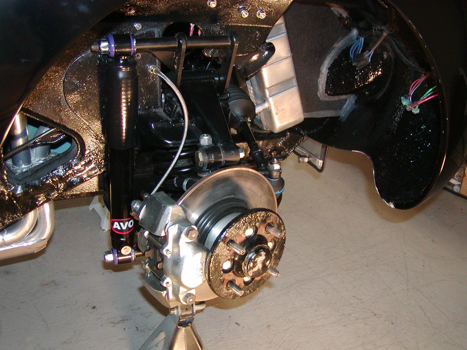
Aftermarket Frontline tube shock conversion.

Low street view of four-link coil-over-shock conversion.
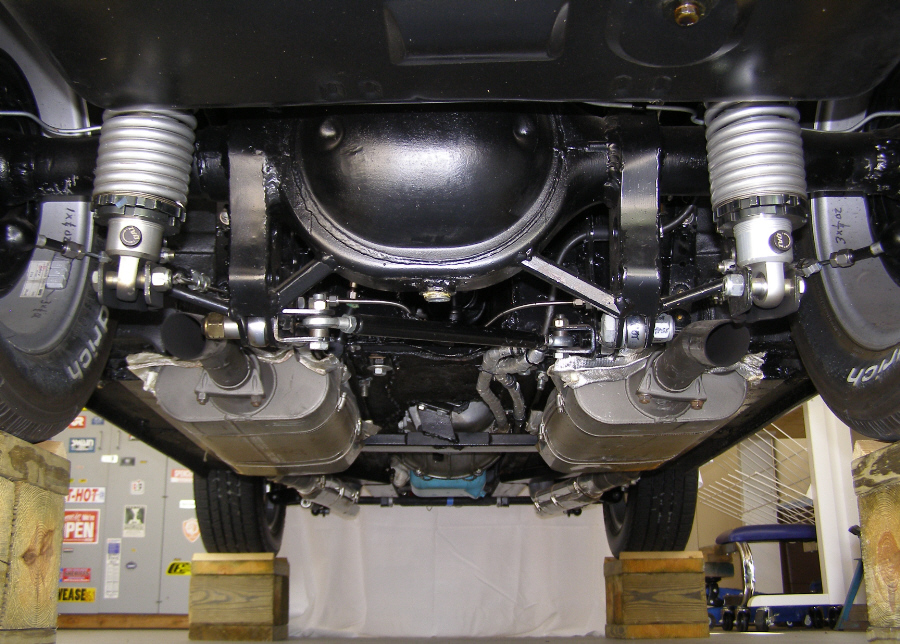
Rear view of four-link coil-over-shock conversion.
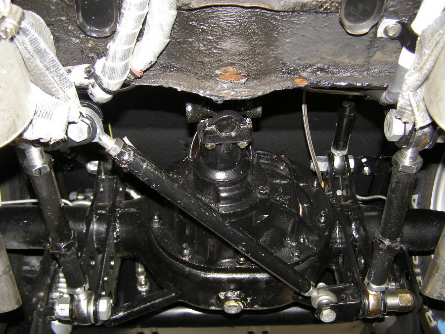
Front view of four-link coil-over-shock conversion.
Driver side view of four-link coil-over-shock conversion.
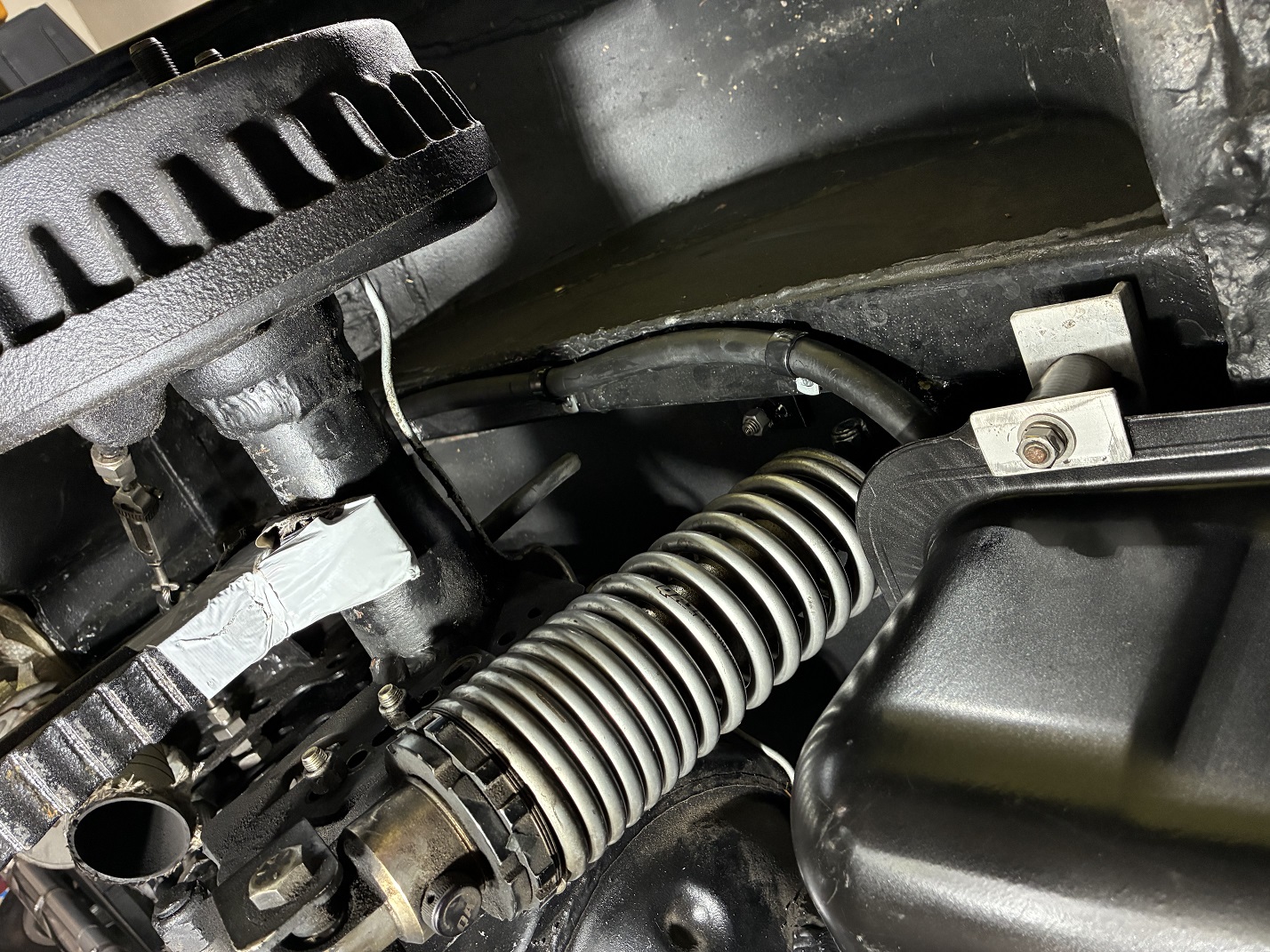
Coil over shock mounting details.
Engine Modifications
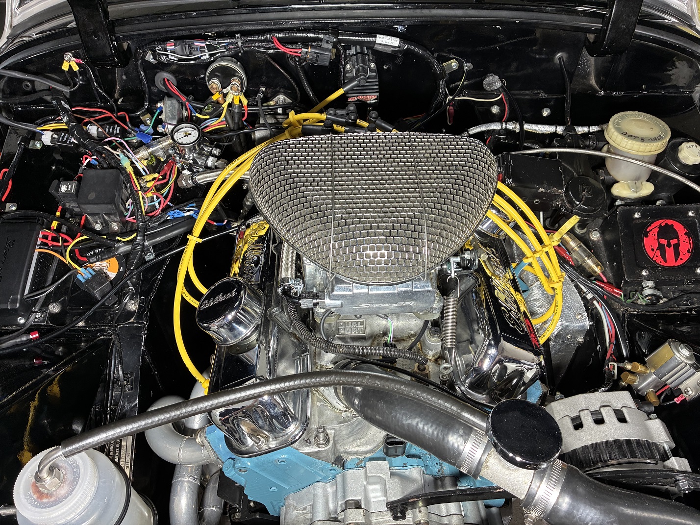
GM 2003 3.4L V6 top side view. 9.2:1 CR, performance cam, Holley Sniper2 EFI.

3.4L V6 underside with cast aluminum oil pan having cross-bolts into main bearing caps.

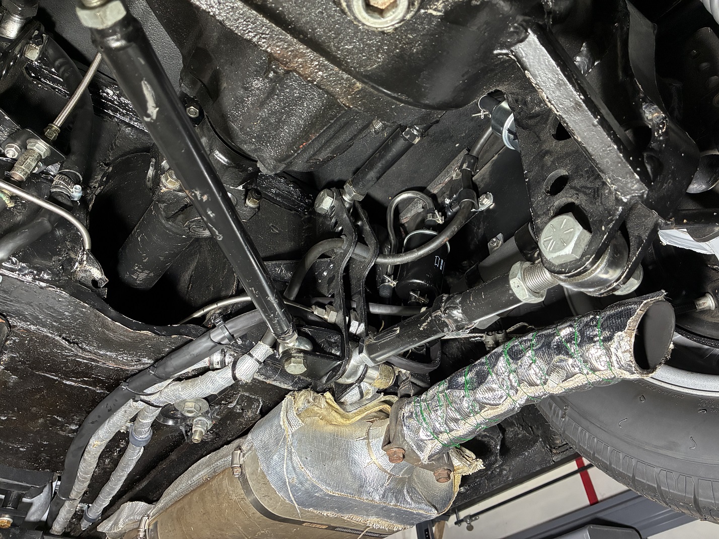
Engine driver side header. Also visible: heavily insulated oil hoses and remote filter.

Holley Sniper2 EFI throttle body and fuel connections.

Holley Sniper2 Power Distribution Module (EFI terminal box).

Sniper2 EFI fuel pump and inlet and outlet filters crammed into limited space.
Fuel lines and filters will be insulated to protect from exhaust heat.

Fuel tank modifications for EFI fuel supply and return lines - close-up of open
access flange added to gas tank for pick-up tube fabrication/access.

Close-up of covered access flange with liberal use of Permatex fuel parts sealant.
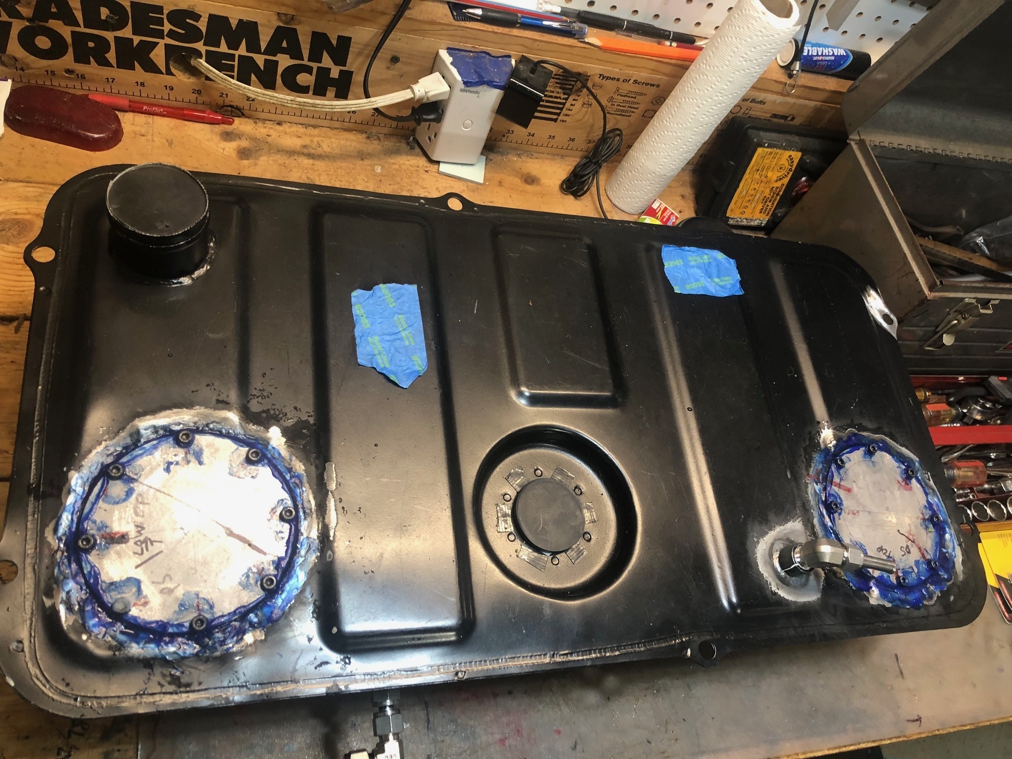
Fuel tank with supply and return line access flanges covered.
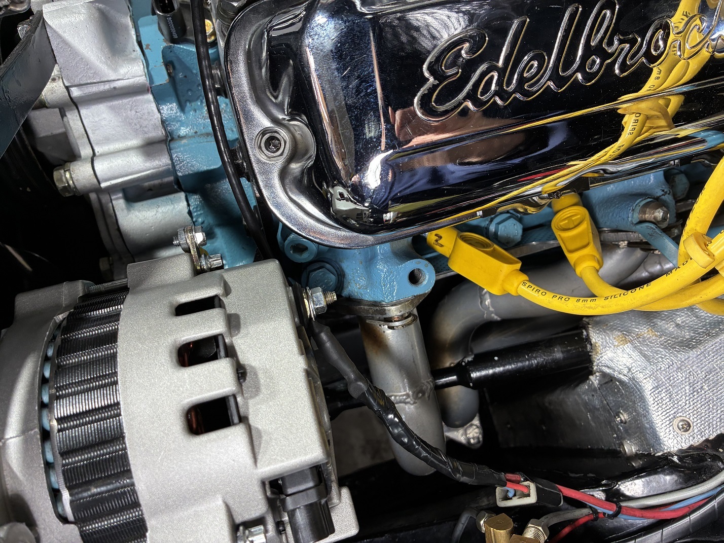
Driver side header close-up.
Also visible: modified steering shaft for header clearance.
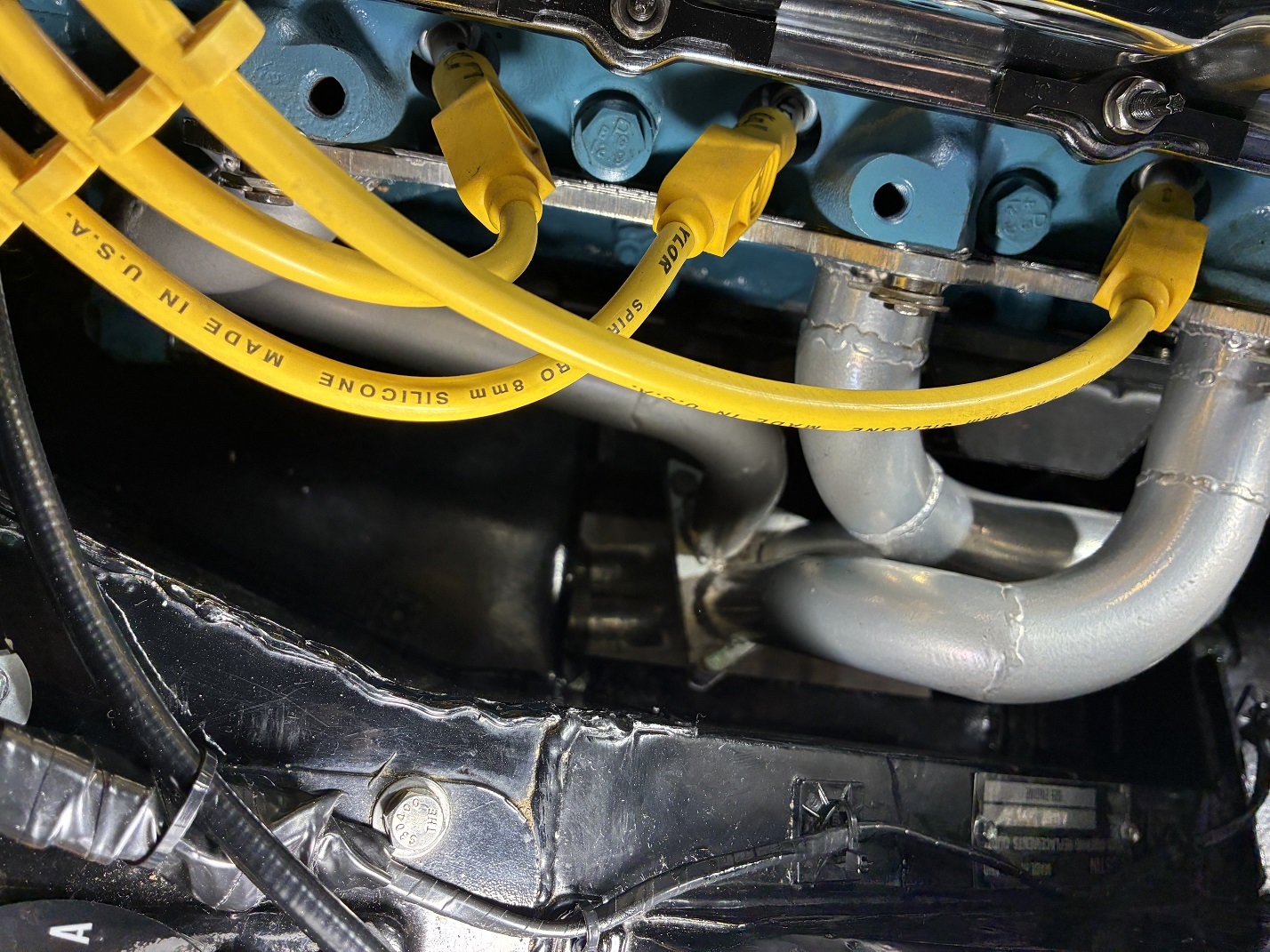
Passenger side header close-up.
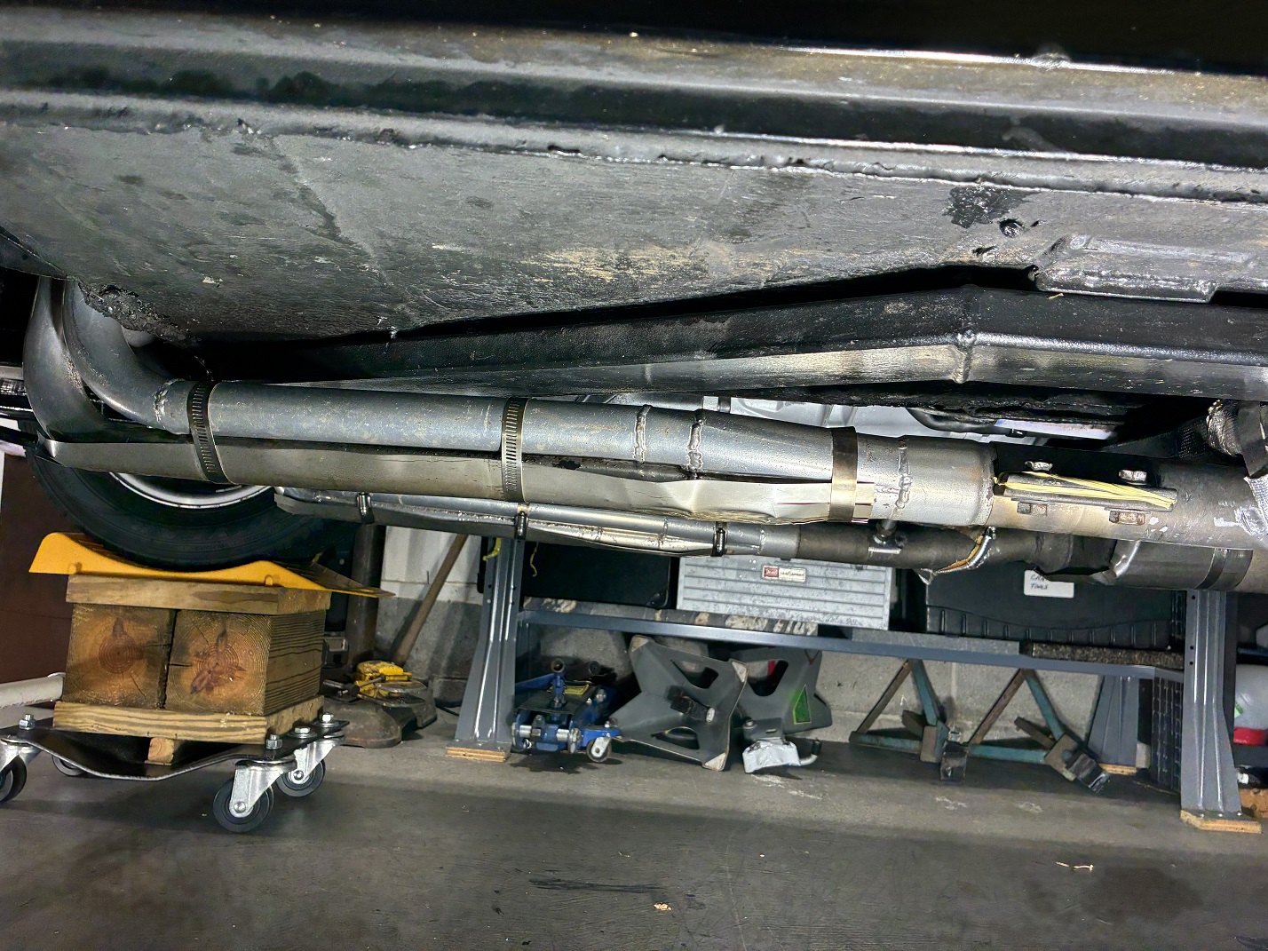
Underside header collectors with replaceable 24 ga. stainless steel skid plates for
protection from scrapes due to low ground clearance.
Header/collector bolted flange joint. Each header is a two piece assembly that forms a long branch header with equal length branches.
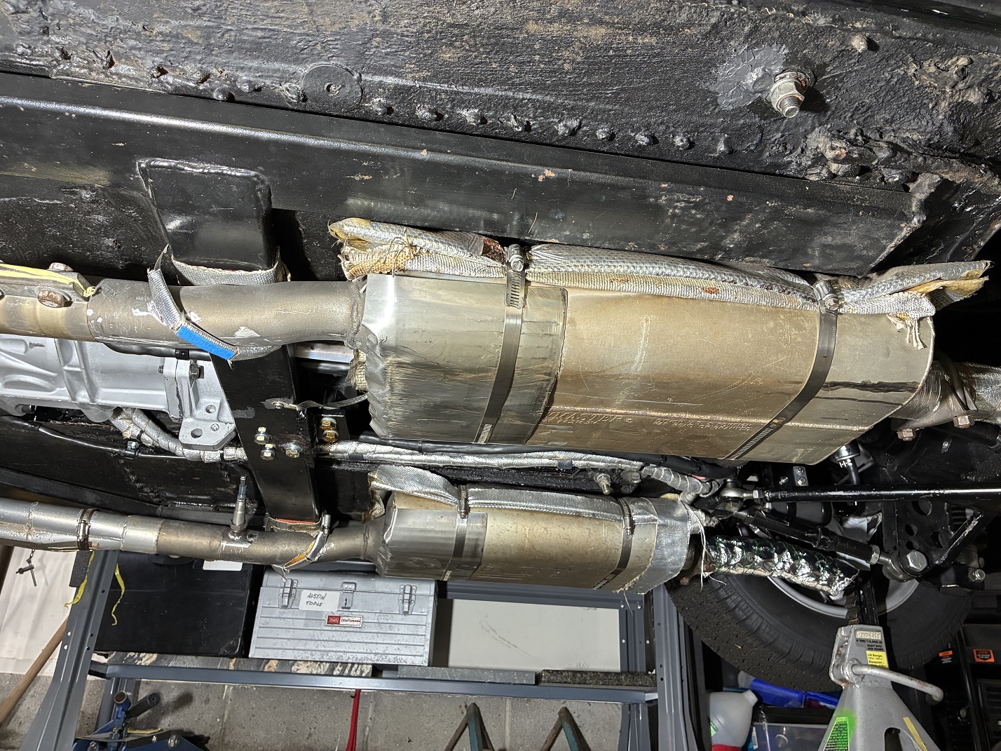
Mufflers with well-worn replaceable 24 ga. SS skid plates and heavy insulation on top to block heat
transfer to the floor boards. The hose clamp is only to support the exhaust pipe when disconnected
from the header collector during work/disconnection of collector.
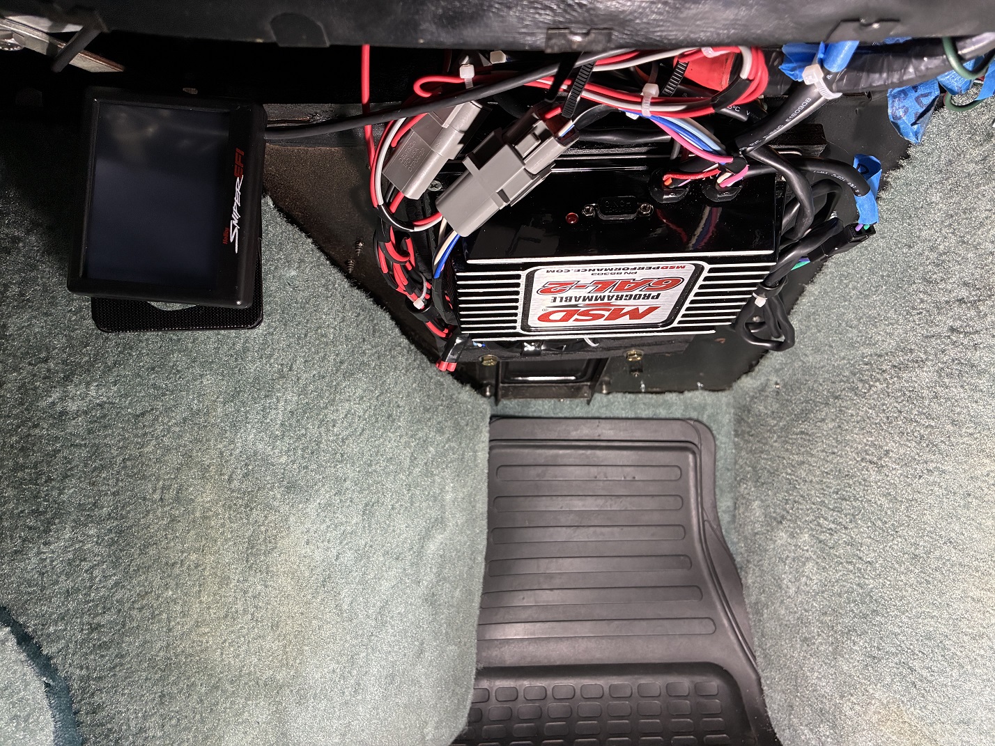
MSD 6AL-2 ignition computer box mounted above passenger side foot well.
Also visible on the left: Sniper2 touch screen for EFI programming stored under dashboard.
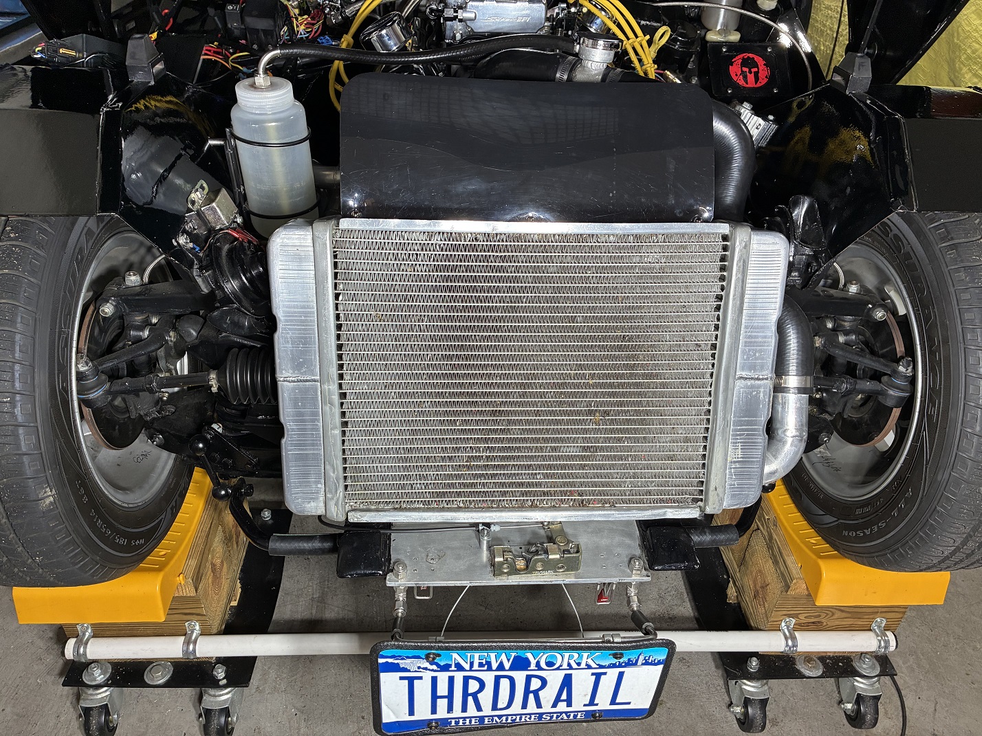
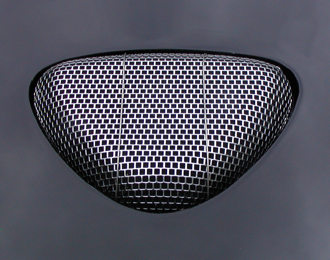
Cross-flow radiator front side with fan safety shield. Also visible: hood latch mechanism on aluminum
plate, operable via connection to the old factory Choke knob on the dashboard. Front tires 185-60R14.

Radiator top hose and filler neck assembly.
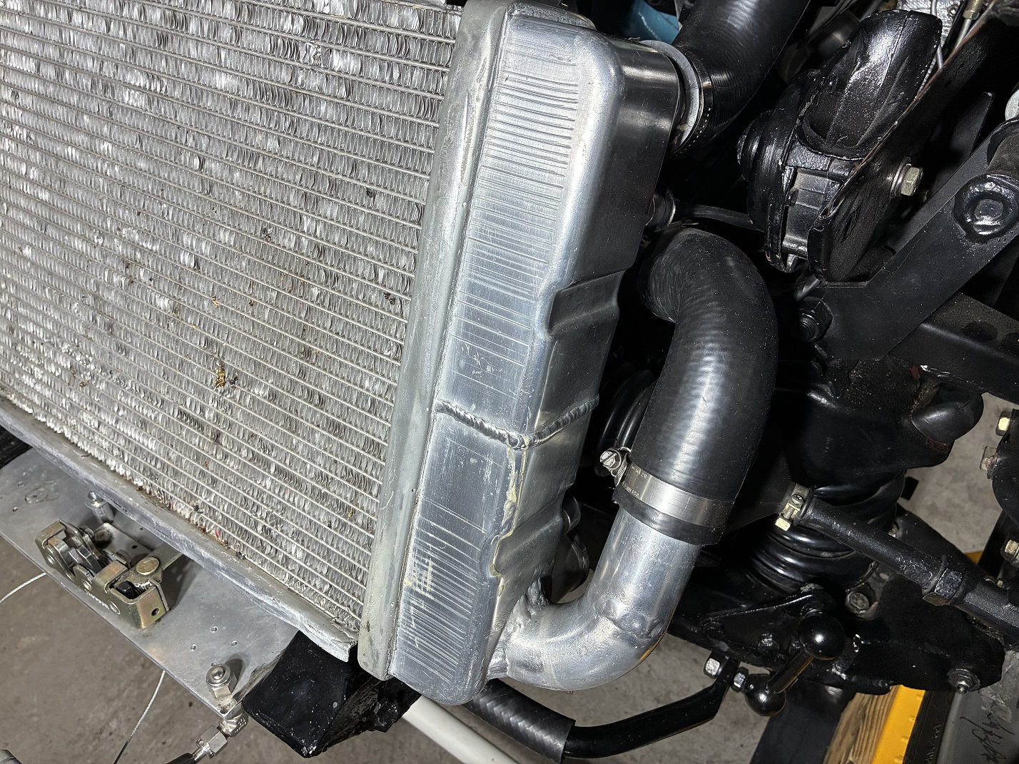
Bottom hose connection to radiator via custom-welded side tubing outlet.

Electric puller fan and back side shroud enabling entire radiator core to have air flow through it.

Hand fabricated hood shroud that forces all air passing through grille to flow through radiator.
Also visible: modified headlight buckets containing halogen bulbs.

Fitment of hood shroud to radiator with hood closed.
Drivetrain Modifications

Rear view of BW WC T5 transmission showing bolting to cross-member.
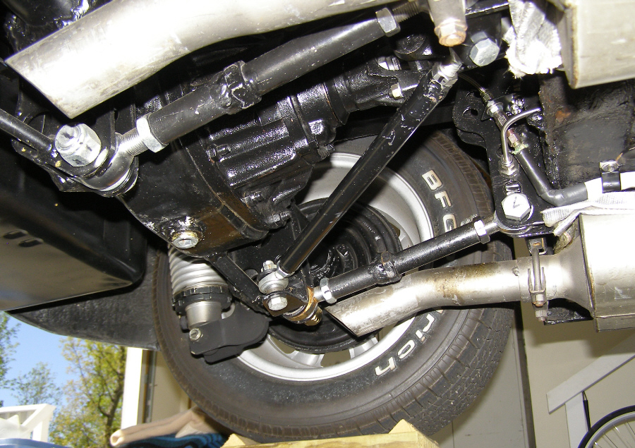
Rear drive shaft connection to 8" Ford rear end. Distance from pinion yoke to transmission too steep
for a dual U-joint drive shaft. The front joint is a CV joint, not visible.
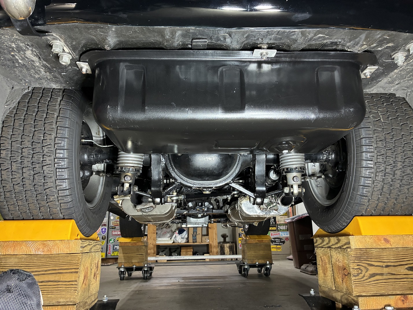
Ford 8" narrowed rear end showing 4-link and coil-over-shock attachments. 3.80 ratio. Tires are
245-50R14. Wheel wells are tubbed to fit them. Also visible: modified OEM 6.5 gallon gas tank.
Clutch and Brake Modifications

Stock clutch and brake master cylinders from a '72 MG Midget, mounted to the left of the factory location
due to narrowed foot well. Clutch MC drives a McLeod HTOB. Brake MC is a dual MC driving the front
disc and 8" Ford rear end drum brakes.
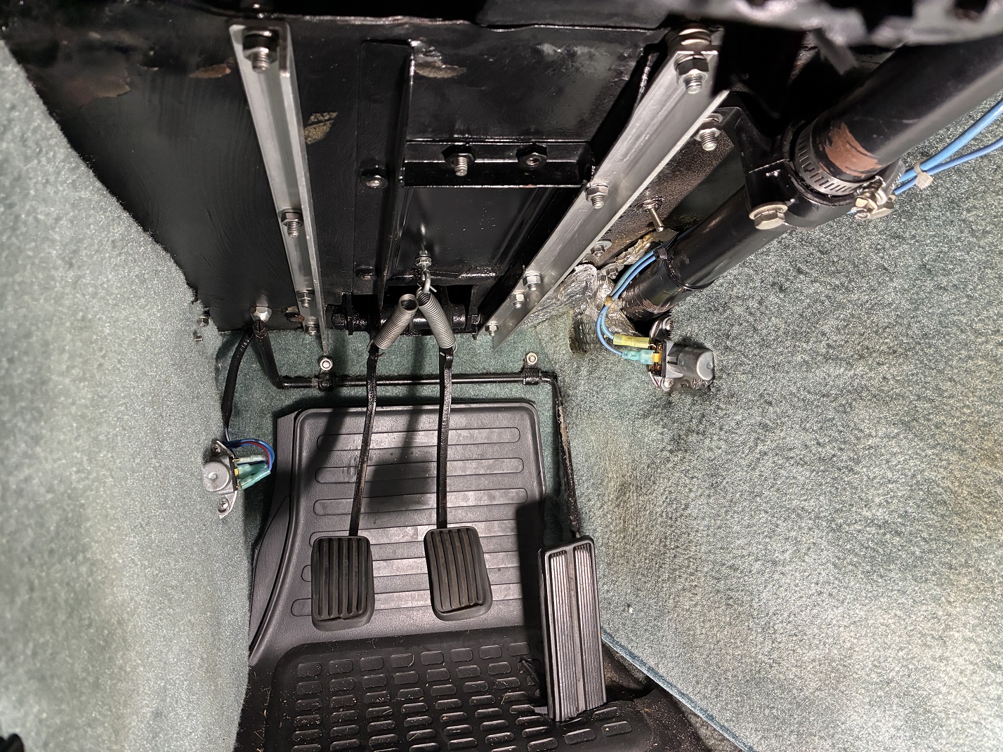
Driver's side foot well. Clutch and brake pedals bent to relocate them to the left. Aluminum angle iron
provides stiffening of the panel that the MC assembly is mounted on.
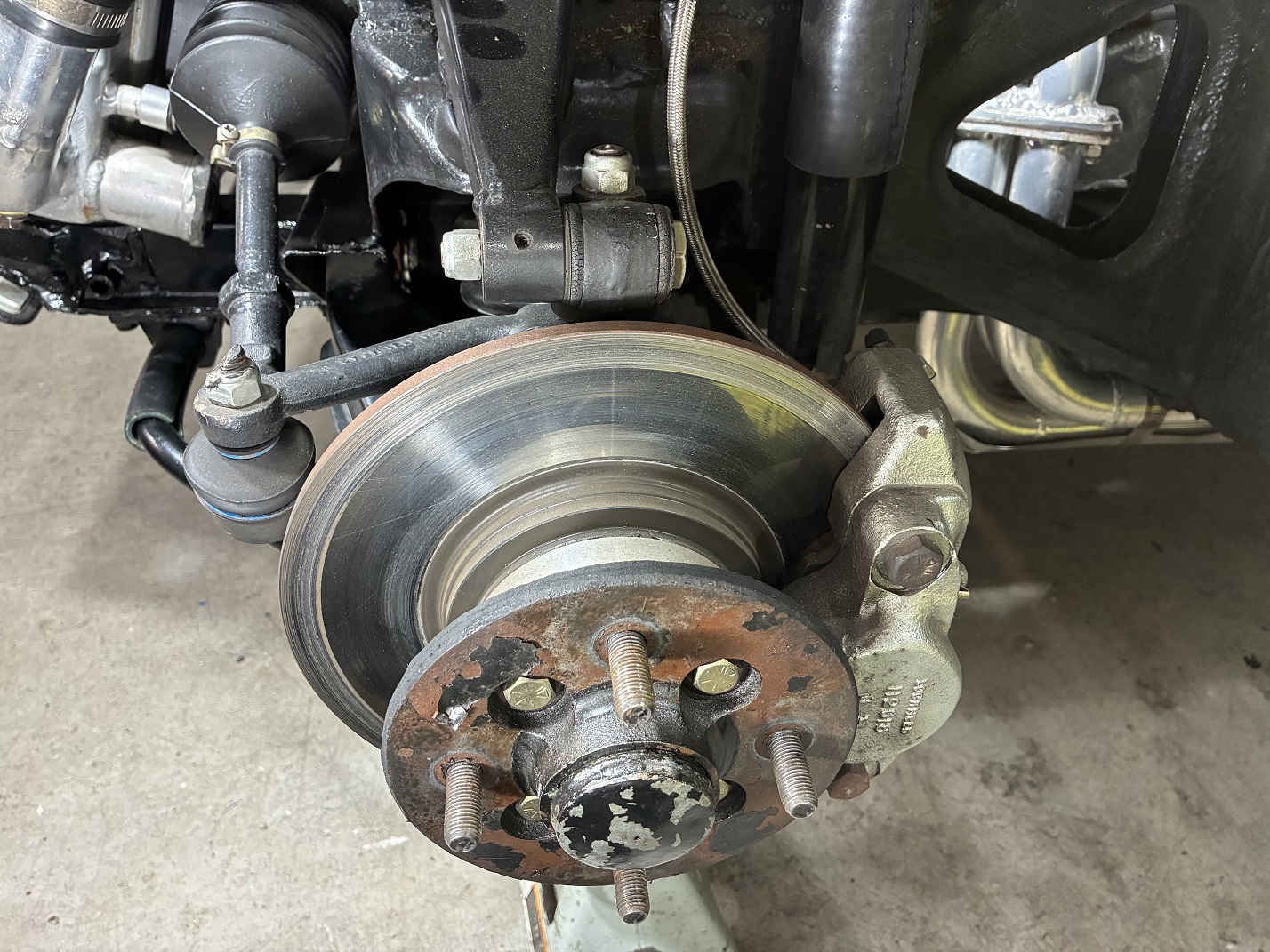
Front brake assembly with Triumph Spitfire rotors and MGB calipers.
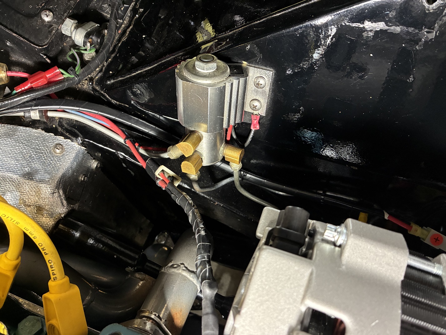
Hurst "Roll Control" for locking the front brakes on during drag race staging area burnouts.
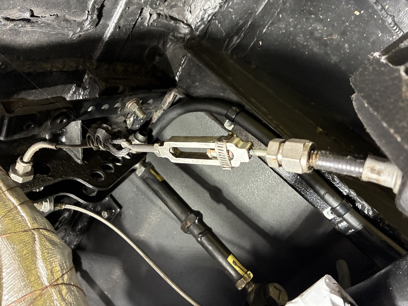
Emergency brake cable assembly with cable exiting SS tubing and turnbuckle for cable tension adjustment.

Emergency brake cables routed through SS tubing and compression fittings. SS tubing central pieces have
gentle 90 degree bends to direct cable up through drive shaft tunnel to emergency brake cable lever. Also
visible: fuel lines, brake line, and battery cable heavily insulated to protect from exhaust heat.
Electrical and Instruments

Aftermarket Painless Wiring fuse box in upper left of photo. Also visible: Sniper EFI electronics box with cover.

Moroso master shutoff switch in left of photo. Also visible: remote oil filter, MSD coil.
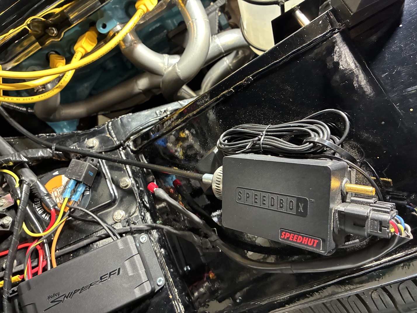
Speedhut speedometer drive box; input is electrical signal from transmission, output is mechanical cable drive.
Interior
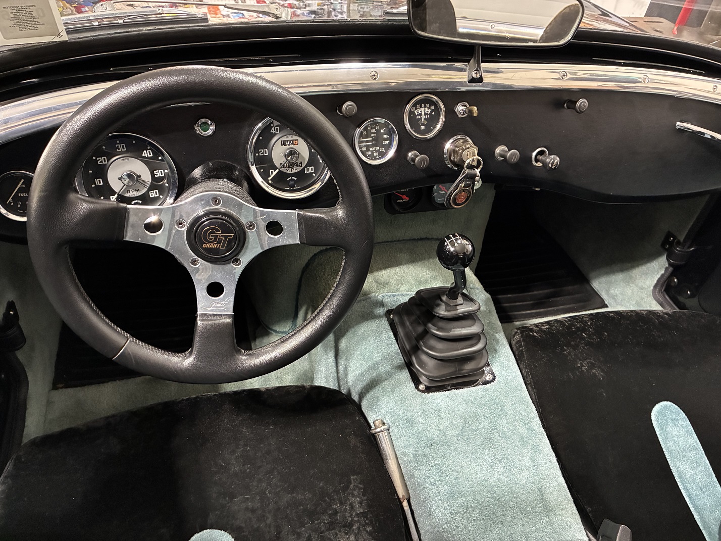
Overall view of dashboard and interior and Hurst billet shifter with shortened and re-bent stick.
Vacuum and voltage gauges added below dashboard.

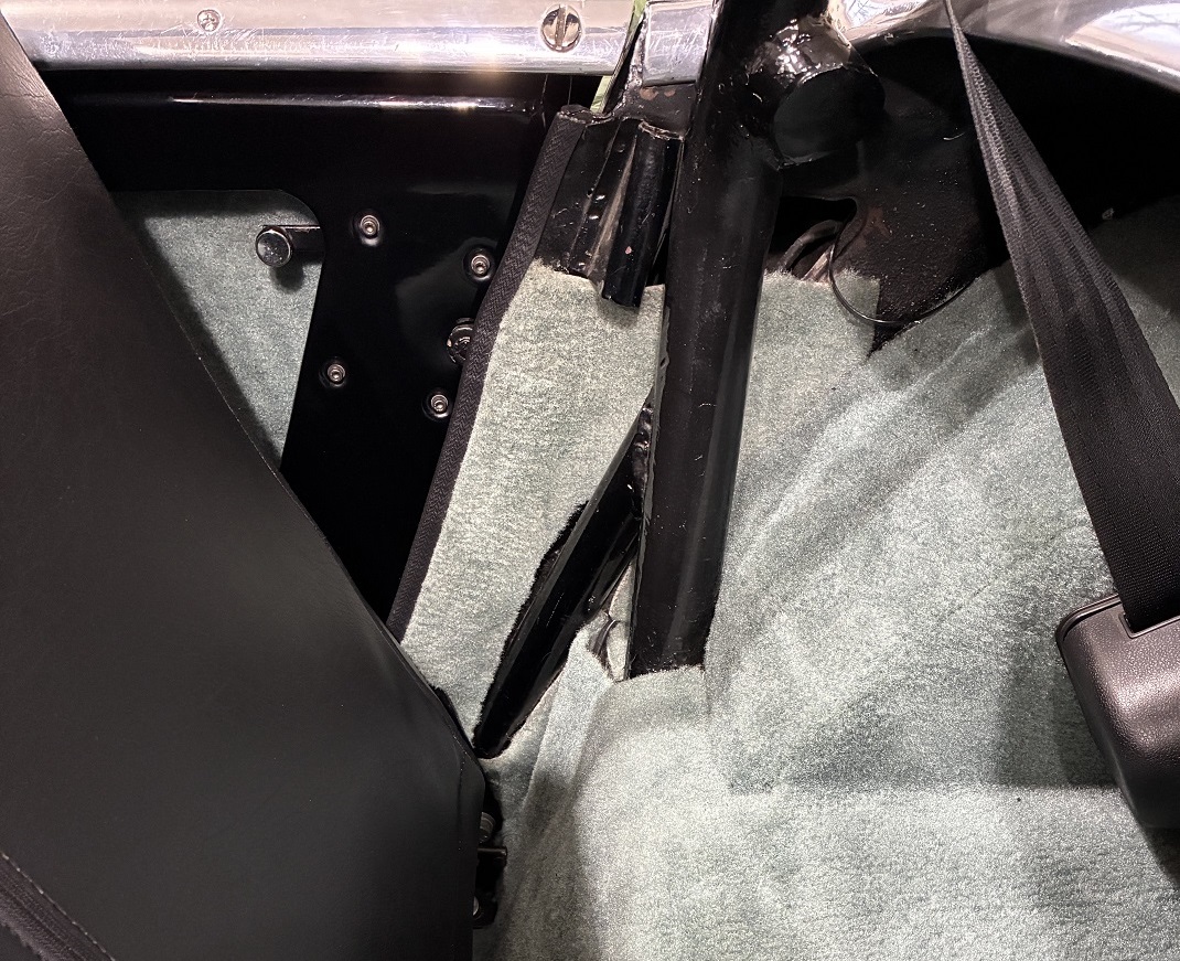
Three point seat belt and custom upholstered Honda DelSol high back bucket seats, showing some
patina/fading from 25 years of occasional sun exposure.

Seat belt anchoring to frame and roll bar.
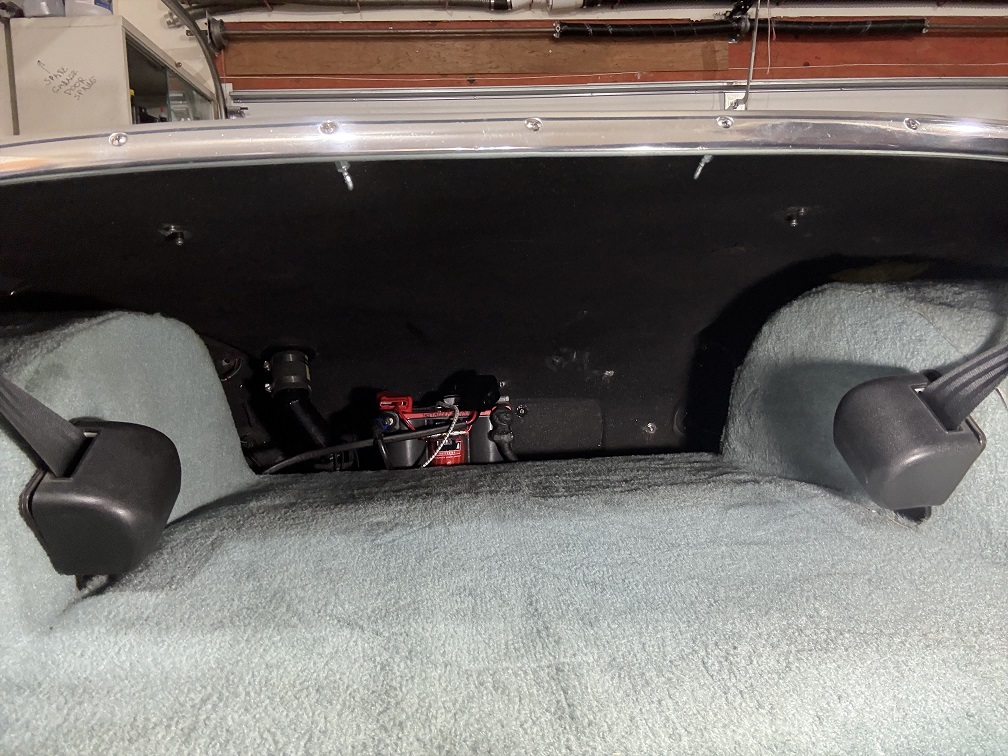
Finished trunk containing well-secured battery.
Body/Exterior
Air cleaner showing through hood. Cutout has a 2-inch wide 12 ga. steel insert embedded in the
fiberglass to prevent any cracking.

Hood latching pin built into bottom front of hood to engage with hood latch assembly.

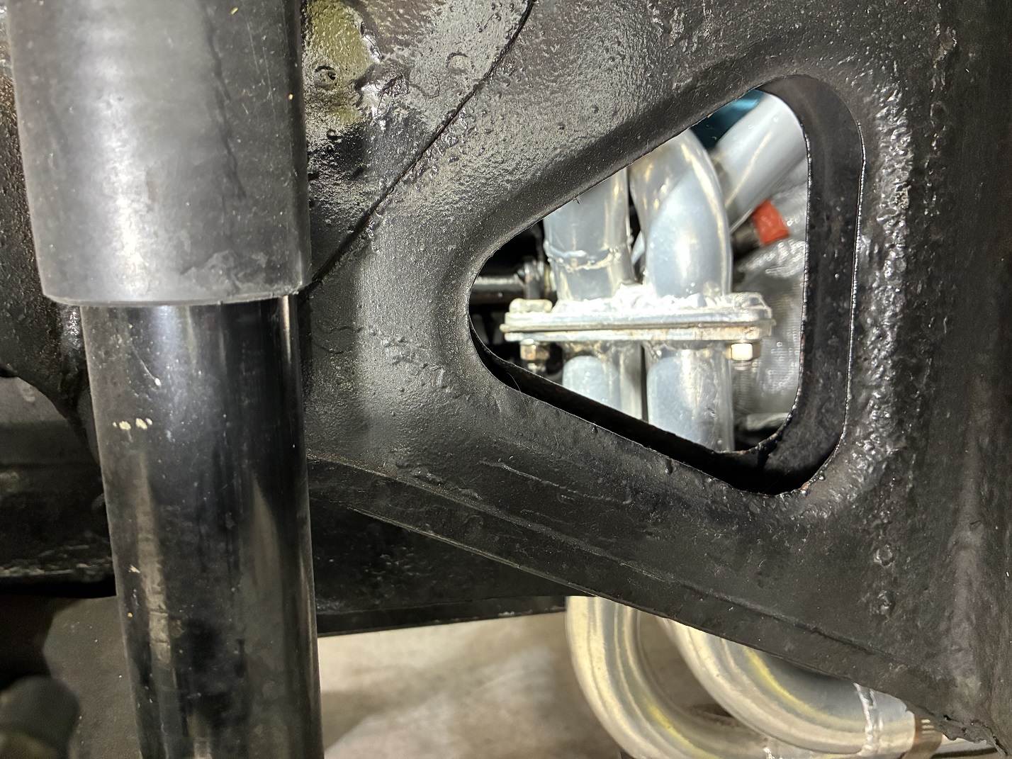
Underside of aluminum plate between frame rails, showing DeStaCo clamps engaged with J-hooks embedded
in fiberglass, for locking hood down. Also visible: heavy duty sway bar and mounting brackets.

Front license plate holder in "static" position (i.e., car not moving). Also visible: hood latch mechanism
behind license plate.

License plate tilted back by air flow when car is in motion.
Third Rail - The Power is On
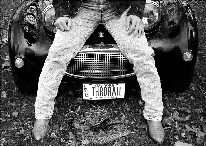
| John supplied the following explaination for how this final picture done: I first got the Austin running well with the V6 on October 1, 2000. We had great fall weather, and I drove it 1000 miles that month. One nice day, I skipped out of work and went home early to take some pictures on our lawn. Back then pictures were taken with film cameras, and you took your roll of film to a shop to be developed. By 2000, you could get digital images on a CDROM along with prints. I had a simple 35mm camera with a little hand held remote, and no other equipment. No tripod. No photo skills. So for this "selfie," I put the camera on a step of a step ladder, and aimed it where I thought it was getting a full view of me. Turned out by the time I took the shot it was aimed a little low.When the prints came back, I thought, well I have to do something with this one. So I edited it a little. |