 �
�
�
 �
�
Dan Master's Triumph TR6 / Ford 302 V8 Conversion
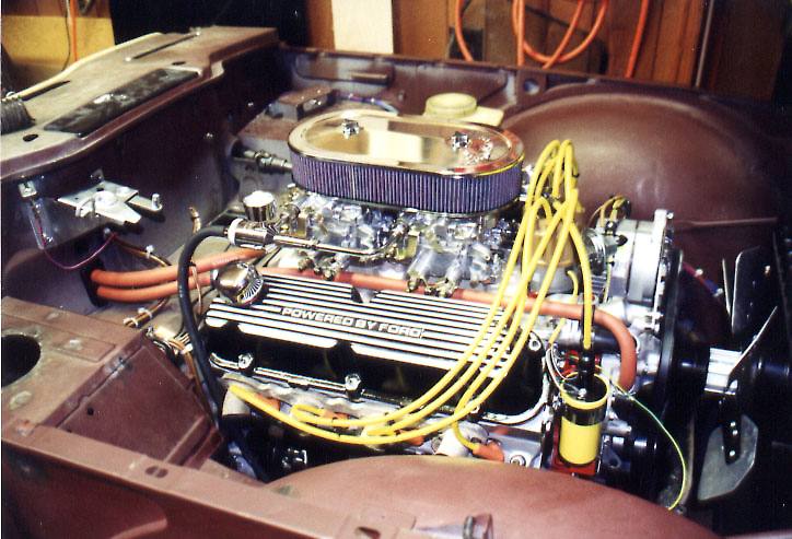
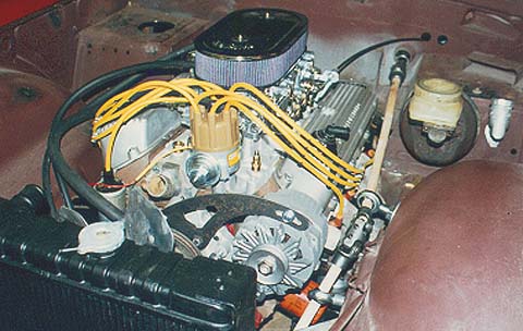
�� A tight fit, but a fit never the less. This is a shot of a later stage of � installation fitment. Except for the headers, there is plenty of room. � Note how the heater hoses mate up perfectly with the TR6 bulkhead fitting.� Not visible is the stock heater control valve, located at the left rear of � the manifold.�
�ENGINE CHOICE
��
Although nearly any engine can�
be made to fit, there are three choices that come readily to mind�
- The Buick/Oldsmobile/Pontiac/Rover aluminum block 215 CI V8,�
the ubiquitous 350 Chevy small block, and the 302 Ford Windsor.�
There are pros and cons to each, but either will work quite well.�
In making a choice, about five factors come into play - outside�
dimensions, weight, displacement, cost, and availability of�
parts, particularly "speed equipment."
�
�
DIMENSIONS: Surprisingly, both the BOP/R and the Chevy engines are �
wider than the Ford, while the Ford is a bit longer than either of �
these. Even though the chart below dosen't show it, I have seen other �
sources which give the height of the BOP/R and the Chevy as an inch �
or so taller than the Ford (and my measurements of the Buick V6 tend to�
support this). I have seen good examples of TR6s with BOP/R, Chevy, �
or Ford engines, so either of the three can be fitted without too much �
difficulty. �
�
�
WEIGHT: The BOP/R is the lightest of the three, while the Ford is about �
90 pounds lighter than the Chevy. What may not be expected, though, is �
that the Ford engine, with aluminum heads, is actually lighter by about�
thirty-six pounds than the original six-cylinder Triumph engine.�
�
�
| �
� The first three entries came from a recent issue of "Street Rodder" magazine, � and are reasonably accurate, except for the weights. Without knowing precisely � what ancillaries are included, a real comparison can't be made for weights. � Length can vary tremendously by the choice of water pump and pulleys, and� height will depend on the intake set-up. The fourth entry was obtained by � subtracting the weight savings of aluminum heads from the third entry. The last � three entries came from my own measurements, and are very precise. The weights � given include everything required to make the engine work - starter, alternator, � flywheel, clutch, intake, carburetors, exhaust, distributor - everything except � oil and water! In this trim, the weight for the Ford in entry two becomes 519 � pounds, from actual measurement! The BOP/R and Chevy weights will most likely� go up a similar amount in the same trim.� | �
�
DISPLACEMENT: The displacement of the BOP/R starts at 215 ci, and goes up to 275 ci in the later�
Rover versions. Stock, the small block Chevy displaces 350 ci, but can be punched out to 400 �
or so if so desired, while the Ford is 302 ci, and can be stroked to 347 without problems. �
�
COST: Cost figures are hard to come by for the BOP/R, but the Chevy will cost a fair amount less�
than a comparable Ford, just because of the greater popularity of the Chevy. I would estimate, �
for lack of actual data, a cost differential of about 10 to 15 percent between the Ford and the�
Chevy.�
�
In my personal opinion, when all four factors are evaluated, the Ford engine comes out as the�
engine of choice. Width and cost rule out the BOP/R, and the additional 90 pounds rule out the �
Chevy. The engine I am using in my conversion is the aluminum head GT-40 engine from Ford Motor �
sports. It comes with the high performance B-303 cam, and is rated by Ford, based on dyno �
testing, at 320 HP. This is with EFI, so I may be getting a little less by using dual quad �
carburetors, but in a TR6, this still comes out to be just a little under eight pounds per �
horsepower - more than enough!�
�
�
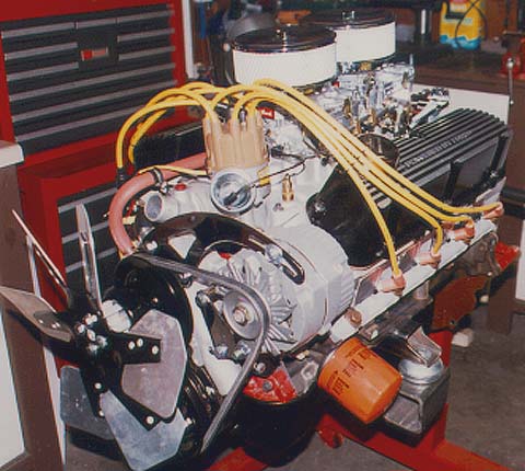
Right side of the engine, with a clear view of the motor mount and the custom �
crank pulley. The engine mount will be turned 90 degrees from shown and welded �
to the Triumph frame.
�
�
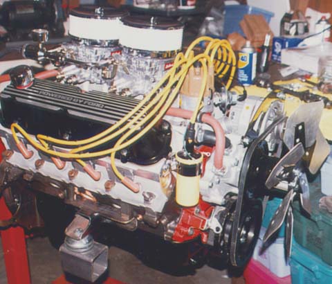
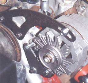
Left side of the engine, showing the custom alternator mounting details and the �
engine mount. I haven't decided whether to use two round air cleaners or one oval.�
�
I know I would be better off using fuel injection, or at the least, a single carburetor, but I�
wanted the "look" of the dual quads simply because when I was younger, dual quads were the hot �
setup. This car is as much about nostalgia as it is anything else. To compensate for the�
excessive carburation, I am using a progressive linkage. When putt-putting around town, �
I will be using only two barrels. When I get my foot into it, all eight barrels will be �
hosing gas into the engine.�
�
ENGINE LOCATION/INSTALLATION
��
The principle goal in locating the engine should be to get it as far back and as low as�
practical. The firewall and legroom concerns limited how far back�
I could place it, and ground clearance limited how low I could�
go. By placing the battery in the trunk or other location, the�
engine can be placed a couple of inches further back than I did,�
but one of my design goals was to retain the stock battery�
location. Trunk space is far too valuable to me to lose any for�
the battery, and I don't like the looks of a side-mounted battery�
under the hood. In the final configuration, the bottom of the pan�
is flush with the bottom of the frame, and the stock TR6 frame�
brace runs between the fan and the engine. I have about 1 ½ inch�
clearance between the fan blades and the radiator. The centerline�
of the crankshaft is about 2 inches lower than in the stock TR6�
engine, and the center of the intake manifold is about 1 1/2 �
inches to the rear. All and all, not a bad arrangement.�
�
The only significant problem�
with the Ford engine, when compared to the Chevy, is the�
auxiliaries sticking out the front, as the result of the�
distributor and the oil pump being front mounted. Almost all Ford�
engines have a long crank pulley, which would strike right smack�
into the TR6 steering rack. This problem can be solved by moving�
the rack forward, but I was afraid to do this for fear of messing�
up the steering geometry. The one guy I have talked to who took�
this approach says he has a little bump steer, but not so much�
that he can't live with it. Personally, I want none, so I moved �
the engine back as far as I could and made a pulley myself to fit�
(I have a friend with a machine shop - very handy). You could�
always have a pro shop make one for you if you don't have access�
to a machine shop yourself.�
�
�
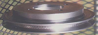
This custom made pulley was required to fit the engine into the engine bay, without �
interfering with the steering rack. There is approximately 3/4" clearance between�
the pulley and the rack - just enough to allow for changing the fan belt without moving �
the steering rack.�
� I'm using a '77 Buick pulley on the water pump, one I just happened to have laying around (no� longer available, unfortunately), and a GM alternator. I put the� alternator on the driver's side of the engine to reduce the� overall engine length, which meant I had to custom make all the� support brackets. Using the Buick water pump pulley as the� starting point, I made the crank pulley to match, and then� followed through with the alternator mounts to get the alternator� to line up with everything else. �
��
�
Not shown are the chromed spacers over the bolts, which were�
made from the left over piece of the Borgenson steering�
shaft used to modify the steering setup. The brackets�
have since been chrome plated, and look sharp!�
�
For motor mounts, I used 2'"X 2"X 3/16" angle iron, with�
2"X 2"X 3/16" tube steel welded perpendicular to the�
angle iron. I notched the end of the tube steel at a 2 1/2-degree�
angle to match the engine/driveline angle, and had a pro weld it�
for me. I cut a nice curve into the outer ends of the tubes so�
they wouldn't look too homemade. I then bolted a rubber-biscuit�
type motor mount bought from a Street Rod shop to these. I used�
pieces of 3"X 3"X 1/4" tube steel welded directly to�
the frame, and the rubber biscuits bolt to these. �
�
I set the engine as low as I�
could without having the oil pan drop below the frame rails. This�
requires me to put a small bulge in the hood, about 1 3/4"�
max, which I kinda like. Not big enough to draw the attention of�
joy-riding teens (they'll never know what hit 'em!), but enough �
that a TR6 enthusiast would notice. Sorta like a "Danger" sign!�
�
�
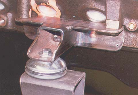
My home made motor mount! The piece of tube steel at the�
bottom will be welded to the TR6 frame rail, 90 degrees�
from shown here.�
�
I modified the oil pan (dual sump) to eliminate one of the oil�
drain plugs. The front plug fell right over the crossmember. It�
would not have been hard to get to, but the oil would drop onto�
the crossmember during an oil change, and would make a mess,�
unless I used some kind of wacky funnel or something. To get�
around this, I cut the center of the pan out and replaced it with�
a fabricated piece of sheet metal. The front sump now flows into�
the rear sump and I can drain the oil just by the rear plug. This�
also adds a quart or two to the oil capacity - not a bad thing to�
do. It was just one of those things that will make the car a�
little easier to live with later.
�
�
The engine could, I believe, be dropped another inch or so by further �
modifying the oilpan and redoing the oil pickup. This, and using a �
single carburetor with a small air cleaner, would eliminate the �
need for the hood bulge. Doing this would require modifications to �
the frame brace and further modifications to the front crossmember, �
but certainly not a difficult task.
�
�
Ford "Shorty" headers will not work, because they exit to the rear of the�
engine and dump right into the firewall. I bought a set of�
"Block huggers", but they didn't hug the block close�
enough - about 3/4 inch more is needed. Also, the tubes at the�
top did not clear the body. I cut the tubes off, leaving only a�
1" stub, and will have a muffler shop custom fabricate the�
remainder. I have mocked them up with 1 1/2inch heater tubing, so�
I know they can be fitted. I also bought a Ford Motorsport�
compact starter for more clearance. It has the added advantage of�
having the solenoid on the starter instead of on the fender (I�
intensely dislike the Ford fender mount solenoid!)
�
�
The mufflers will fit in the�
space provided for the stock muffler. I am not just sure yet how�
the exhaust pipes will run from the headers to the mufflers, but�
I don't foresee any major problems. They may run just a�
little low at the front, till they clear the engine, but after�
that, I think they will tuck up between the frame rails like the�
stock setup. �
TRANSMISSION, CLUTCH, AND DRIVETRAIN
�� For clutch actuation, I am using a Tilton hydraulically operated throw-out bearing. They� slip over the trans input shaft, and operate like a slave� cylinder. I am using a T5 transmission from an '88 Mustang for� mock-up purposes, but I have later model with a higher torque� capacity for actual installation. It is larger (no doubt!) than� the stock unit, but it is actually lower than stock. I cut down� the transmission tunnel quite a bit. There will be room to mount� electrical components over the tunnel if desired.�
��
�
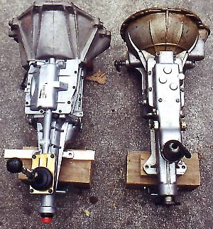
Guess which one is stock? Note the tilt of the T5. The mounting�
flange, though, is level, and fits perfectly to the TR6�
mounting pad. The rear crossmember will have to be moved�
a bit to match.
�
 �
�
�
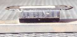
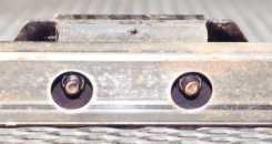
Two views of the transmission crossmember mount, made from�
a piece of 1" X 2" 16 Ga. steel tubing.�
Note the holes for access to the bolts. The transmission�
mount is a stock TR6 piece, with mates perfectly to the�
T5 mounting holes.�
� The '88 is rated at 265 lbft, while the new ones are rated at 330 lbft. I haven't purchased the� Tilton unit yet, so I don't know if the TR6 MC will work, or if I� will have to use a Tilton unit. The cost is roughly the same,� since I will need to rebuild or replace the one I have. Using the� stock Ford cable clutch actuator should be fairly simple if you� want to go that route. TR4s used a different arrangement for the� clutch MC, with the MC running to the rear instead of to the� front as on the TR6. It should be fairly easy to get the parts� from a TR4 from a junkyard, and make an adapter to connect to the� Ford cable (I say this, having never tried it! It may not be so� easy, but worth looking into). The only real problem with this is� the space taken up by the throw-out arm at the bell housing - it� will cut into the foot room quite a bit. �
�HANDLING AND BRAKING CONCERNS
�� A lot of people are concerned about the additional weight of the Ford unit over the stock TR6� engine and the effect it will have on handling and braking. As a� matter of fact, with aluminum heads, water pump, and intake� manifold, a lightweight performance flywheel, and the small� starter, the Ford engine/transmission combo weighs 25 pounds LESS� than the stock TR6 engine and transmission. A stock Ford engine� with iron heads and intake will weigh about 90 pounds more, or 65 � pounds more than the TR6 engine. I plan on using up-rated shocks,� springs, and sway bars front and rear, but don't plan on any� other serious modifications. Even though the car will be capable� of much higher speeds, since I will be driving it only on the� street, I will not be going much faster. And, as the car will not� be any heavier, the stock set-up should be plenty adequate. The� typical "Street Rod" uses a 10" rotor on the� front, and the hi-po rods use an 11" rotor. The stock rotor� on the TR6 is 10 7/8", so, considering that the average� street rod weighs over 3000 pounds, and the TR6 weighs only 2500,� the stock brakes don't look so bad. According to the brake� experts, a street driven car should have 200 square inches of� brake swept area per ton: The stock TR6 has over 250! Never-the� less, I am looking into using Wilwood 4-pot calipers to match the� braking power of the 11 inch drums that I got with the Ford rear� axle (compared to the stock 9 inch units). I will either have to� improve the fronts or add a proportioning valve to reduce the� rears to get the proper front/rear bias. I don't want the rears� to lock up first in a panic stop! �
��
�
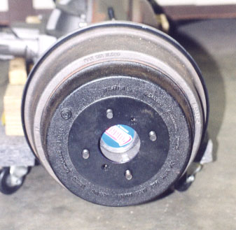
The stock 9" drum is placed over the 11" Ford drum�
for comparison. There should be no trouble hauling�
down a lightweight TR6 with these, especially with�
upgraded front discs to match!�
REAR END
��
Depending on the power output of your engine, and its intended use, the stock rear end may well�
be adequate. When these cars were raced, the engines produce�
around 200 HP, so they are known to withstand power levels of�
that magnitude. Even with only 200 HP, though, drag racing would�
probably shorten their life considerably. With 200-250 Hp, and�
driven moderately - no dumping of the clutch at 3000 RPM - the�
stock rear should live a long, healthy, life. I know of at least�
two cars that use the stock differential, one that has been on�
the road for over ten years with no problem. As an economy move,�
the stock rear end could be left in place and up-dated later as�
time and money permit.
�
�
Installing a complete, narrowed, IRS unit from a Jag or a Corvette, or even the aluminum�
IRS set-up from a Lincoln MKIII, should not be a terribly�
difficult job, but would be very time consuming if you did it�
yourself. There are several companies that specialize in�
narrowing the Jag and Corvette units for use in early Ford,�
Chevy, etc, street rods, so the tread width would not be a�
problem. As is, though, the stock TR6 frame will not work with�
these units, as there is no "kick-up" in the frame in�
this area as there is in the street rods. The entire rear section�
of the frame would require reconstruction.
�
�
For drag racing applications, a live axle, utilizing a four-bar set-up, will work very well.�
There are several companies specializing in this set-up, so�
getting parts would be no problem. This configuration can be�
set-up to handle over 1000 HP - or more - so it would be bullet�
proof in this application.
�
�
There is one serious drawback to the last two options, at least for my application - both will�
cut into the trunk space and/or the passenger compartment quite a�
bit. Depending on intended usage of the car, this may or may not�
be a problem, but it is something to be considered.
�
�
For my application and intended usage, I decided to use a narrowed Ford 9-inch axle. I�
am using the complete rear suspension set-up - springs, bushings,�
hangers, etc. - from a TR4A, live axle version. It is almost a�
bolt-in operation, requiring only a little welding at the rear�
hangers. I cut the rear spring/bumper/body mounts from a TR4A and�
replaced the same units on the TR6 with them. It was an�
incredibly easy task. All that was required was to grind down the�
welds and remove the tube crossmember from the TR4A mounts, and�
grind the TR6 mounts off of the TR6 frame. I slipped the TR4A�
mounts over the TR6 crossmember, and welded them in place. If you�
can not find the front hangers, and they are scarce, fabricating�
them should not be a major task. The rear hangers are the same�
whether the TR4A is an IRS or a live axle version, so they should�
be easy to come by. If not, it would be very easy to modify the�
TR6 mounts by welding on metal tabs with the extra holes required�
for the rear spring shackles. �
�
�
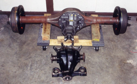
What it takes to handle over 300HP! Compare the Ford�
9" to the stock differential in the foreground.�
The Ford 9" measures 52 inches from drum to drum.�
�
There are many companies which specialize in narrowing Ford axles, so�
getting one will not be a problem. I bought mine from Currie�
Enterprises in California, complete with brakes, brake drums, and�
a Truetrac limited slip differential. This is a gear type�
differential, which supposedly doesn't give the understeer�
effects that a clutch type does. I will maintain the stock TR6�
bolt pattern (4 X 4 1/2"), but I will use ½" studs,�
rather than the 7/16" stock size. This will allow me to use�
one spare tire instead of two, and will let me use Panasport�
wheels, which is my preference.
�
�
The only thing I don't like about this approach is the limiting effect of the leaf�
springs. The outside-to-outside measurement for the springs is 41 1/2". Using �
215/65R15 tires, the tread will measure 50 3/4", compared to 49 3/4" stock, and �
the outside sidewall-to-sidewall dimension will be 59". This is 2"�
more than stock with the same size tire, so the fenders may need�
to be flared a little. A little I don't mind - I just don't want a large flare.
�
�
If you have the time, before you get to that point, you should start reading "Street�
Rodder" magazine; they usually have one or two cars using�
the Jag or the Corvette in each issue, and there are lots of�
advertisers, whose ads can be quite helpful. �
STEERING
�� As with any engine swap,� re-routing the steering can be a bit of a problem. I shortened� the outer steering column to where it only protrudes about an� inch beyond the firewall. The inner column is in two parts -a� smaller diameter inner shaft, and a larger diameter hollow outer� shaft. I cut the outer shaft in two, just above the collar for� the steering wheel locking mechanism (if you wish to keep the� lock mechanism, you could cut just below the collar). I then cut� a Borgenson steering shaft, with splines on one end and the other� end plain, to the right length. I used my friend's machine shop� to turn down the plain end to fit inside the hollow shaft, and� had it professionally welded. �
��
�
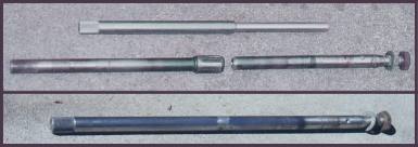
In the upper photo, the top piece is the Borgenson shaft,�
turned down, and the lower piece is the stock TR6 shaft,�
cut in two. The Borgenson shaft was inserted into the TR6�
shaft and the two pieces were welded together, bottom�
photo.�
�
I cut the outer column close to the firewall to keep the angle as shallow as possible to�
eliminate interference with the left hand cylinder head. At the�
other end, I used a Borgenson U-joint, with splines to match the�
TR6 rack on one side and the standard 3/4" on the other. I�
could not get by with only three U-joints, so I used a double�
U-joint in the middle of the steering assembly. This required me�
to use two Heim joints. I drilled a hole in the shock tower for�
the lower Heim joint, and drilled a hole in the inner fender for�
the upper joint. The Borgenson catalog says not to use sheet�
metal for a support, but I discussed this with the owner of�
Borgenson (a very nice guy, and very helpful, BTW), and he said�
it would be no problem as long as I had the first one solidly�
mounted. There is a lot of shock transmitted to the steering gear�
when you hit a bump, and the sheet metal just won't stand up to�
it. I am also using the solid aluminum steering rack mounts, so�
that should reduce the shock to the fender mounted Heim joint to�
near zero.
�
�
It's too early to tell for sure, but the steering seems just a tight, and as free, with�
the four u-joints as it did before. I don't expect a�
problem. Once again, looking to the street rod fraternity,�
multiple u-joints are used regularly with, apparently, no�
problems. �
�
�
Photo taken early in the mock up process. I used wooden dowels�
to make the steering line up determination. Notice also�
the new radiator, which will be replaced with a Griffin�
aluminum cross flow unit.�
COOLING
�� For cooling, I had a thick core, five-row radiator made to the same dimensions as the stock� unit, but I was not happy with this idea. I have now bought a� Griffin aluminum cross flow radiator, with two 1- inch tubes, and� a larger surface area. This will require me to notch the frame� rail and build a new support structure for the radiator. My� original plan was to use a mechanical fan, but I will now be� adding an electric unit with a thermostatic control. I prefered� the mechanical fan for reliability - if the engine is running,� the fan is also - but the mechanical fan didn't mate up real well� with the radiator, as it stuck up about two inches or so over the� radiator, and building a fan shroud would have been a bit� difficult. With an electrical fan, there are several ways for it� to fail, leaving me stranded with an overheating engine. A blown� fuse, a bad relay, a bad wiring connection, or just a bad fan� motor, will do it. As long as the car is moving at a reasonable� speed, it will be OK without the fan, but Murphy's law being what� it is, the most likely time for a failure is in the middle of� town, in a traffic jam, in August! The electric fan will provide� more efficient cooling because I will be able to locate it better� with respect to the radiator than I could the mechanical unit. �
��
�
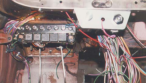
What a mess! When completed, the wiring will be up out of the�
way of the fuse panel. Note the Aluminum switch panel�
used in place of the original switch plinth. The switch�
to the left is for the headlights, the middle hole is for�
the hazard switch, and the ignition switch is on the�
right.�
ELECTRICAL
��
The electrical work involved should be fairly straight forward, unless you go the route I did.�
I removed the fuse box and relays from under the hood, and made a�
new fuse/relay/flasher panel and mounted it up under the pedal�
box, where it is out of sight, yet easy to get to. (I am a�
retired electrical engineer, so this part of the job was the�
easiest for me). This panel has eight fuses, two flashers, and�
five relays.
�
�
The fuses are of the aircraft/industrial type. The cap twists to lock and unlock, and�
the fuse comes out with the cap. I used these simply because I�
like them. I don't know of any real advantage to them for�
automotive use. I used eight fuses because that is one less than�
the number required to properly fuse the car. In addition to�
these eight, I used, by design, one in-line fuse in the lighting�
circuit. My wiring is not that much more complicated than stock -�
Triumph just used six fuses too few!
�
�
There are five relays, one each for the starter, driving lights, and fuel pump, and two for�
the alarm system. I built in the wiring for the alarm system,�
using an eleven-pin connector. When I install the alarm unit, I�
will cut off the wires that come with it to a length of just a�
few inches and terminate them in the other side of the eleven-pin�
connector. Then it is just a matter of plugging it in. If I ever�
change out the alarm unit, no changes to the wiring will be�
required. This approach also has the advantage of having all the�
alarm wires wrapped in the wiring harness along with the other�
wires.
�
�
The two flashers are, of course, for the turn signals and the hazard flasher.
�
�
I made my own wiring harness, using the proper colors and sizes for the TR6. I used a mixture�
of connector types; some were typical British types, and some�
were of the typical American type. The selection depended on the�
application: where connecting to, for example, the stock TR6 turn�
signal switch, I used British "Bullets." Where�
connecting to the headlight switch, which is a GM unit, I used an�
American type. Connections to the hazard switch - vintage Radio�
Shack - are soldered. �
GAUGES
�� With the exception of the� tachometer, the original gauges can be used, although I would not� recommend using the ammeter, if your car has one. The stock� ammeter is a 30-amp unit, and must be replaced with at least a� 50-amp unit, which will probably not match the other gauges. I� would replace the ammeter with a voltmeter, which is a very� simple task. The fuel and water temperature gauges can be used as� is, and adapters are available to connect the mechanical oil� pressure gauge to the ford block. A new speedometer drive gear� will be used at the transmission to correct the speedometer� readings. The TR6 tachometer is a mechanical unit, and a Tach� drive distributor for a Ford engine is very expensive. Of course,� one option is to leave the stock Tach in place for appearances,� but just not hook it up. Adapters will be needed to connect the� transmission to the TR6 speedometer cable, or to connect the Ford� speedometer cable to the TR6 speedometer. Although not common,� adapters should be available from some of the major instrument� shops. �
��
�
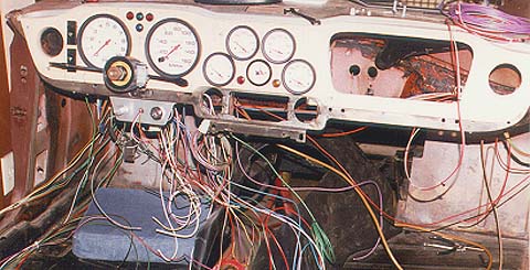
I like those gauges! The dash panel used here is a plywood�
mock up just for construction purposes.�
� I used a complete set of Autometer Phantom gauges - black bezels with white faces - and� made my own dash from a piece of solid Oak. The Tach and the� speedometer are 5 ½ " units, while the smaller gauges are 2� 5/8". Because of the size of the smaller units, I had to� make my own dash. The dash has been the biggest headache so far.� Only minor mods were required to the metal dash backing to use� the larger gauges, but the woodworking involved in the wood part� were significant for me. Cutting the glovebox door out of one� piece of wood, and not having a large or uneven gap was a real� chore. Of course, the dash and door could be made from two� pieces, and covered with one piece of veneer, which would greatly� simplify things. �
��
�
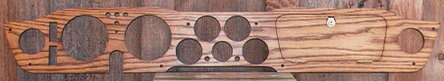
This is the actual dash. The discoloration in the center is�
from the flash unit on the camera. It looks much nicer in�
person!�
� There is another option available now, which wasn't when I bought my gauges. Autometer� now makes gauges in the Phantom line that fit in the same holes� as the stock TR6 gauges. Using these, with the larger Autometer� Tach and speedometer, should allow you to use the stock dash. The� large Autometer units will fit in the stock openings, but they� are a "loose" fit. There will be about a 1/16" gap� all around, in the recessed area.�
�BODY MODIFICATIONS
��
I don't plan any body�
modifications other than that required to make the swap. I am�
quite happy with the car's lines as is, and don't know�
of anything that I think should be changed.
�
�
Most likely, I will have to flare the rear fenders, and the hood will require a slight bubble. The�
bubble will need to be about 1 3/4" high at the front, and�
about 3/4" high at the rear to clear the air cleaners. I made�
it 19" wide and 26" inches long for appearance sake. I�
could get by with a much smaller bubble, about 7 X 13, and only�
about 1" high, but I don't think that would look as�
good. I am not planning on having a scoop in the bubble. I intend�
for the sides to slope gently into the hood itself. I very�
carefully cut the 19 X 26-inch piece out of the hood and I will�
use it for the top of the bulge, as it already has the correct�
contour. I made hammer forms from pieces of oak, and I will form�
the front, rear, and the sides over these.
�
�
At the firewall, I had to do a fair amount of cutting, and I will have to fabricate a sheet�
metal replacement. Even though I had to make fairly large cuts,�
very little legroom is lost, and none where it counts. �
�
�
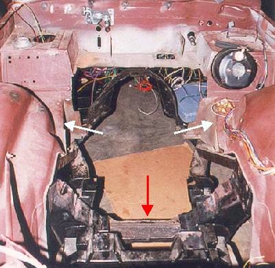
Not as bad as it looks! A narrower battery and a fair amount�
of sheet metal work will be required, but very little�
legroom will be lost. This is the only surgery required�
to fit the engine (notice that the inner fender�
"wings" were cut down for more room - white�
arrows). No cutting of the floordoards was required.
�
The red arrow points to the crossmember notch. A new cover will�
be welded in place, and tube steel reinforcements will be�
welded to the bottom for strength. The crossmember will�
be strong enough to serve as a jacking point for the�
front of the car without damage.
�
�
The transmission protrudes into the cockpit only a little more then stock. Because of the�
cutting, I lost the original gas pedal mounting, so I am going to�
use a pedal from a Street Rod vendor - Lokar - and mount it to a�
bracket, which will be welded to the pedal mounting assembly. The�
bracket is a simple "L" shaped piece of 1/8-inch steel,�
and the pedal bolts to this. This will operate a cable that�
protrudes through the firewall shelf where the wiper motor is�
mounted. The #8 spark plug will be a tight squeeze to change, but�
it can be done. I'll have to use a ratchet instead of a sparkplug�
wrench, but certainly no problem. If it's too tight, I may opt to�
add an access door from the interior to get to this plug.
�
�
Because I hate to stop for gas, I am replacing the stock 12.5-gallon gas tank with a�
19.5-gallon tank, custom made to fit in the same location as the�
original. I made the tank as large as I could without intruding�
into either the trunk or the cockpit. I do a lot of long distance�
travel, so I need all the trunk and interior space I can get. The�
dimensions of the tank are 32.5 X 12 X 12 X 10 (the bottom is�
wider than the top). A little surgery was required on the cockpit�
bracing, and a piece of sheet metal with strengthening ribs�
pressed into it will replace the original diagonal braces. The�
interior upholstery panel will be replaced with a pair of custom�
panels. The bottom panel will be straight, while the top panel -�
about four inches, will curve as the original to allow space for�
top stowage. �
�
�
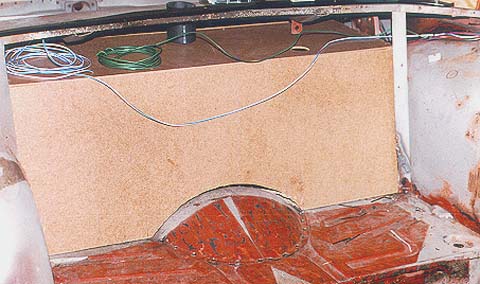
I made a mock up of the fuel tank out of Masonite to ensure�
a good fit with no intrusion into the trunk or cockpit.�
Take my word for it - you cannot get any more gas tank�
into this space and still be able to get it in and out!�
The tank will hold approximately 19.5 gallons, as�
compared to the stock 12.5 gallons.�