 �
�
�
�
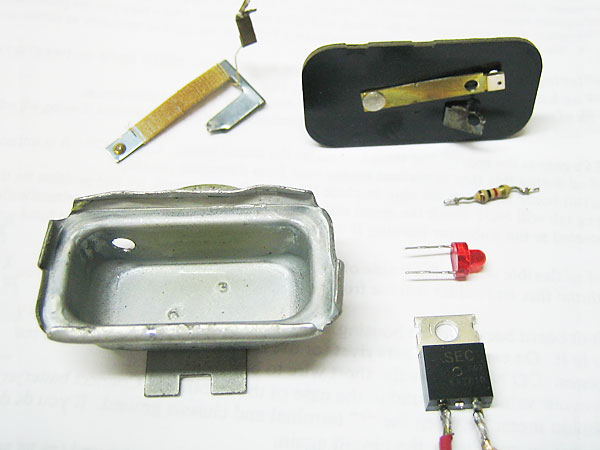
Upper left: the resistance-wire wrapped bimetallic element of an old-fashioned thermal Voltage Stabilizer.
�
Lower right: a solid-state electronic voltage regulator that can be used to replace it.
�
How To: Replace Your MGB's Thermal Voltage Stabilizer
�Install a Solid State Regulator Inside the Lucas Case
� as published in BritishV8 Magazine, Volume XVI Issue 2, October 2008�� text by: Curtis Jacobson
� photos by: Jim Miller�
�
� Notes: this article references MGB equipment, schematics, etc., and the information� may not be transferable to other vintage cars. �
�Background Information
��
Are you using original fuel level and coolant temperature gauges on your 1968�
or later MGB? Unlike modern aftermarket gauges, these two old-fashioned gauges �
are thermal ("bimetallic") devices. Their indicator needle is connected to a short �
beam constructed of two dissimilar metals. The beam is wrapped in resistance wire, �
which warms-up proportionally to the amount of electrical current passing through it. �
The gauge needle's position is determined by flexion of the beam due to the differing �
thermal-expansion rates of the two metals. To work properly, the MG fuel level and �
coolant temperature gauges need to be used with an external Voltage Stabilizer. �
(Note: the 1968-1972 MGB oil pressure gauge is also a thermal device. However, �
because of the unique nature of its sensor, it doesn't require a Voltage Stabilizer.) �
�
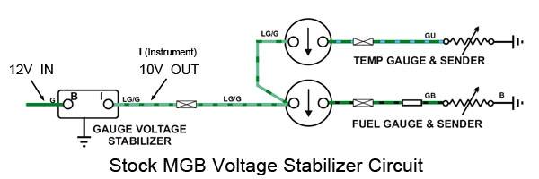
The schematic drawing below, "Stock MGB Voltage Stabilizer Circuit" illustrates �
how the fuel and temperature gauges are wired. In summary, the gauges are designed �
to receive a constant supply voltage of 10 Volts and it's the job of the Voltage �
Stabilizer to provide it. The fuel level and coolant temperature sensors, downstream �
of their respective gauges, are connected through their mountings to chassis/ground. �
The sensors act like variable resistors; their resistance changes with fuel level or �
coolant temperature respectively. �
�
The Voltage Stabilizer itself is nominally provided 12 Volts. However, we know from �
experience that the "voltage in" isn't so stable or predictable! A number of factors�
affect the supply voltage available, including: the battery's state of charge, the �
output of the generator or alternator at any given moment (which may be affected �
by engine RPM), and whether various loads on the system are "on" or "off". �
�
�
Please support the sponsoring companies who make BritishV8 possible, including:
�
 �
�
�
Regardless of how stable or predictable the 12 Volt supply is, the Voltage �
Stabilizer's purpose is to iron things out. As a generalization, you might say: "If �
the Voltage Stabilizer provides more than 10 Volts, both gauges will read high. If �
it provides less than 10 Volts, both gauges will read low." �
�
However, this generalization isn't strictly true - because the original MG Voltage �
Stabilizer doesn't actually regulate voltage at all! Instead, it cycles power "on" �
and "off" to achieve an average voltage (over time) of about 10 Volts. �
If you take an old-fashioned Voltage Stabilizer apart, you'll find a bimetallic �
element with a resistance wire wrapped around it (much like an automatic-reset circuit �
breaker, and not entirely unlike the gauges themselves.) Heat in the resistance wire �
causes the bimetallic element to bend. The bimetallic element actually bends back �
and forth quite rapidly, and in turn it rapidly opens and closes a set of contact �
points. Thus, it switches between a nominal supply voltage of about 12 Volts and �
a disconnected state (i.e. zero volts!) That suits old-fashioned, single-coil �
MGB gauges pretty well because they have a lot of mechanical dampening built �
into them. If your gauges are sufficiently damped, you may not see that their �
needles constantly wiggling as the Voltage Stabilizer chatters on and off; you'll �
only perceive the "average" readings they're showing you. �
�
By modern standards, thermal Voltage Stabilizers are inaccurate and inconsistent.�
Their output varies a lot between summertime and wintertime because their accuracy �
is affected by ambient temperature. Heat under the dashboard (e.g. when your windscreen�
defrosters are turned "on") can cause a significant shift in gauge readings. Output �
may also vary over the life of the Voltage Stabilizer as the bimetallic element �
fatigues, as internal contacts grow dirty, etc. If the resistance wire breaks, the �
Voltage Stabilizer will simply pass-through electrical current at continuous and �
unregulated voltage, so the old-fashioned thermal gauges will read high. �
�
If your Voltage Stabilizer is old or broken, or if you just want to improve the �
accuracy and consistancy of your fuel level and coolant temperature gauges, you �
may want to consider converting to a modern solid-state electronic voltage regulator.�
�
IMPORTANT NOTE: if you replace your original MGB gauges with aftermarket gauges, �
you should probably remove and NOT replace your old-fashioned thermal Voltage Stablizer. �
(Jumper across the Voltage Stabilizer connections.) Modern dual-coil gauges provides �
accurate information regardless of supply voltage, but they may not be adequately �
damped to accomodate the abrupt on/off cycling of a thermal Voltage Stabilizer. �
Shopping List
��
Solid state voltage regulators are inexpensive, but they may be difficult to find �
locally. The easiest places to purchase them are online. "Google" the part numbers �
to identify potential suppliers.�
�
National Semiconductor's "LM2940T-10.0" and NTE Electronics' "NTE1953" are �
low dropout (LDO) solid-state voltage regulators. If you supply either of them �
with a DC voltage between 10.5V and about 30V, they will provide a constant output �
voltage of 10.0V. Similar to an old-fashioned bimetallic Voltage Stabilizer, they�
can't boost voltage: so if the supply voltage drops to below about 10.5V, these �
LDO's will "dropout" and simply pass through whatever supply voltage is available.�
�
Note: there are other alternative voltage regulators that could also be used. One �
example is Texas Instruments' part number "UA7810CKCS" (a.k.a. "7810" or "LM7810")�
which frankly you're probably more likely to find at your local Radio Shack. The �
main advantage of the National Semiconductor or NTE Electronics devices is their �
somewhat lower dropout specification.�
�
Also needed: just a few basics including a soldering iron, solder, about six inches of �
insulated wire, heat shrink tubing (or possibly electrical tape), etc.�
�
Optional extras: a small LED lamp and a 1000 ohm resistor. �
�
�
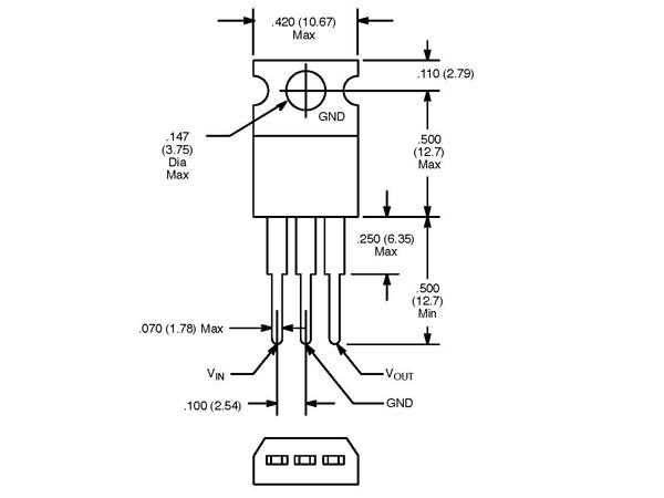
Solid State LDO Voltage Regulator Pin-Outs
�
left-to-right: VIN, "GND", VOUT
�
�
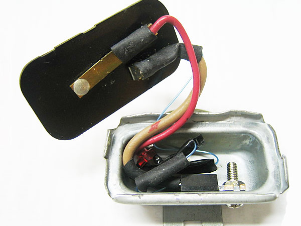
Make sure the solid state regulator is solidly grounded to the metal cover.
�
Directions
��
1. Disconnect the car's battery and remove the original Voltage Stabilizer �
from the car. (Note: the Voltage Stabilizer is mounted on the drivers-side �
firewall just above the steering column.)�
�
2. Open the voltage regulator by carefully prying back the tabs that clamp �
the metal cover to the plastic base.�
�
3. Cut and remove the old bimetallic regulator mechanism, being careful to �
leave enough of the two terminals for soldering wires onto them later. �
�
4. Prepare your solid-state voltage regulator by cutting off the center of �
its three terminals. (This terminal is nominally a "ground" connection, and it�
would be redundant with the mounting tab in our installation. They're connected �
internally...)�
�
Enjoying this article? Our magazine is funded through the generous support of readers like you!
�
To contribute to our operating budget, please click here and follow the instructions.
�
(Suggested contribution is twenty bucks per year. Feel free to give more!)�
�
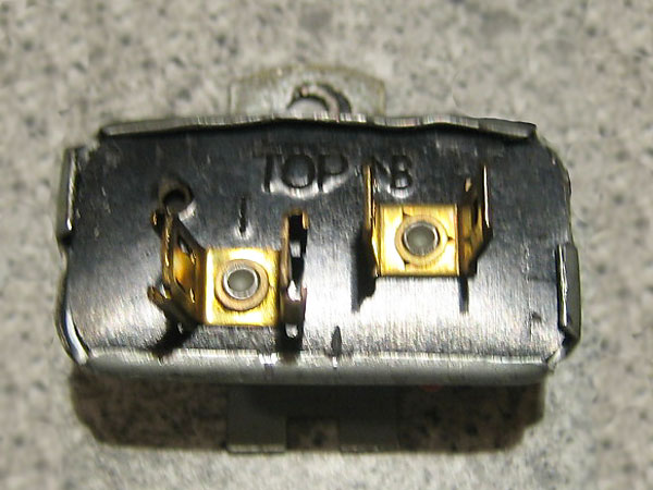
5. Using a short length of wire, jumper between the solid-state voltage regulator's �
VIN (12V in) terminal to the "B" terminal on the plastic base. �
Carefully solder both connections.�
�
6. Using a short length of wire, jumper between the solid-state voltage regulator's �
VOUT (10V out) terminal to the "I" terminal on the plastic base. �
Carefully solder both connections.�
�
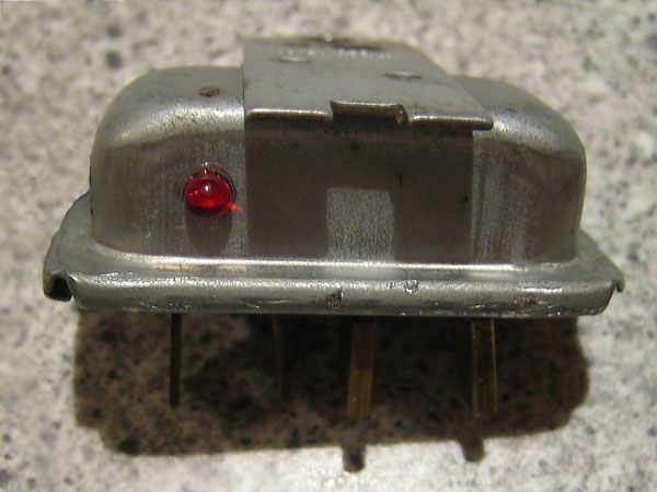
7. The LED indicator is optional. Its purpose is just to show that the system is powered �
and grounded, and that the voltage regulator is functioning. The LED is connected at one �
end to the voltage regulator's 10V "OUT" terminal, and at the other end it's connected �
to ground through a 1000 Ohm resistor.�
�
8. To function properly, the solid-state regulator must be electrically �
well-grounded to the rest of the vehicle. Accomplish this by (first) connecting �
it to the voltage regulator's metal cover with a machine screw and nut. Note: �
the voltage regulator itself must in turn be grounded to the car by its mounting. �
If the fasteners are corroded or dirty, they should be cleaned at this time. �
�
�
Gently fold the edges of the metal cover back over the plastic base.
�
�
�
An optional LED simply indicates that the voltage regulator is powered, grounded, and functioning.
�
� Views expressed are those of the authors, and are provided without warrantee or guarantee.
� Apply at your own risk.�
� Photos by Jim Miller for British V8 Magazine. All rights reserved.�
� The schematic drawing "Stock MGB Voltage Stabilizer Circuit" was derived from an Advance Auto-Wire schematic,
� and was used here by permission.�