 �
�
�
 �
�
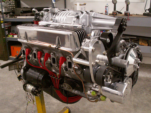
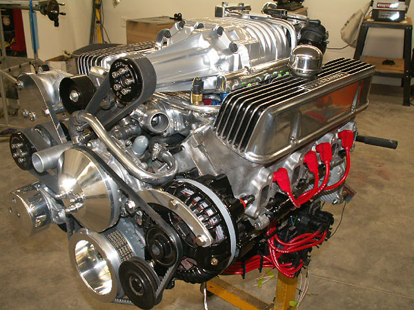
Under-Hood Eaton M90 Supercharger (on an MGB w/ Buick 215 V8)
��
as published in British V8 Newsletter, Volume XV Issue 2, September 2007�
�
by: Bill Jacobson�
�
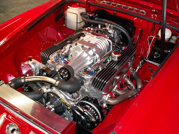
Here are some construction photos of my new supercharger installation. The �
intake manifold, M90 supercharger, and drive system all fit under a stock �
MGB hood (although my hood had already been modified for air cleaner �
clearance.) This installation includes MegaSquirt electronic fuel injection �
and a Ford EDIS ("Electronic Distributorless Ignition System"). It also features �
cowl/cold-air induction. The original Smith's heater housing has been modified, �
and now functions as an air filter housing for the engine.�
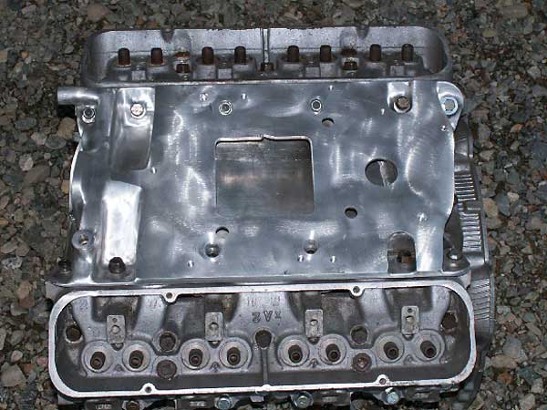
Fabricated Intake Manifold
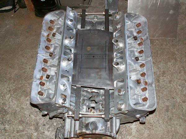
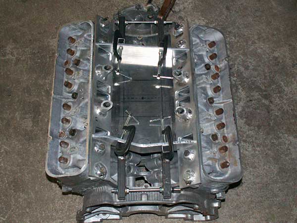
�� The intake manifold pieces were hand-formed, mostly from 1/4" T6061 aluminum. � I have a spare engine block and heads that I bolted together to form a jig. � The plenum bottom and the side plates that mate to the cylinder heads were � constructed first, and I built up from there. Basically I made a few pieces, � jigged them up in position (on the block/heads), and took the whole works � down to the machine shop. �
�� All the TIG welding was done by a local fabrication shop called � "Peterzelka Brothers". After each bit of welding, I brought the manifold � back home, made some more parts, jigged them up, and took them back for � more TIG welding. Finally, the top and sides were machined true on a large � milling machine.�
��
�
The plenum bottom and the side plates that mate to the heads were constructed first.
�
The box-tube structure shown here was just for temporary locating/clamping.
�
�
Beginning to build-up the plenum area...
�
�
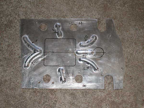
The "top" of the intake manifold, shown upside-down to display vanes...
�
�
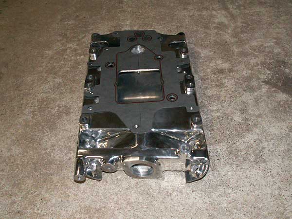
The fabricated intake manifold, finished except for some polishing...
�
�
With the gasket in place, you can better see how the supercharger mates up.
�
This view also shows the thermostat / water neck boss.�
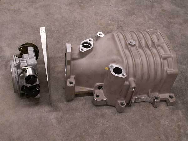
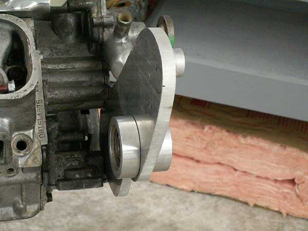
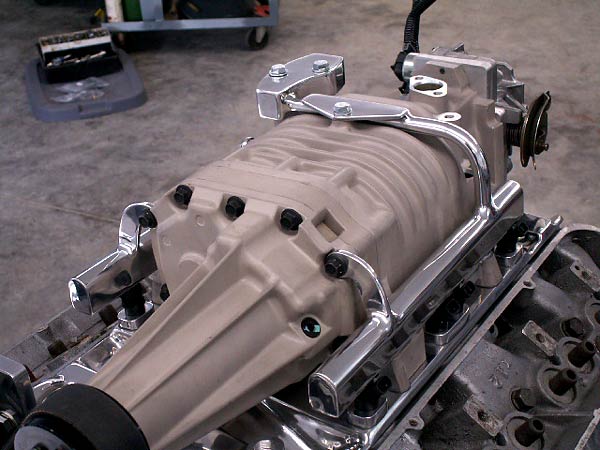
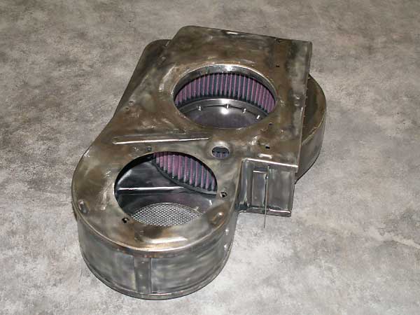
Modified Blower Housing
�� Since the blower was made for a 3800 V6, the blower housing had to be trimmed � slightly to match the Buick 215 V8 port spacing and to allow room for the � Delphi fuel injectors. Fortunately, the blower housing casting is very thick � in this area, which allowed room for the modifications. The inlet angle was � reduced on a milling machine. Then I made an angled spacer plate that points� straight backward for hook-up to the cowl-induction system.�
��
�
Compact throttle body with integrally mounted throttle position sensor (TPS) and idle bypass valve.
�
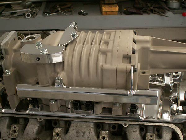
This view also shows the angled spacer plate that points toward the cowl-induction system.
�
Notice that the supercharger housing was modified slightly for fuel-injector clearance.
�
�
1996 Buick 3800 V6 supercharger housing (GM/Eaton M90), modified slightly to fit on a Buick 215 V8.�
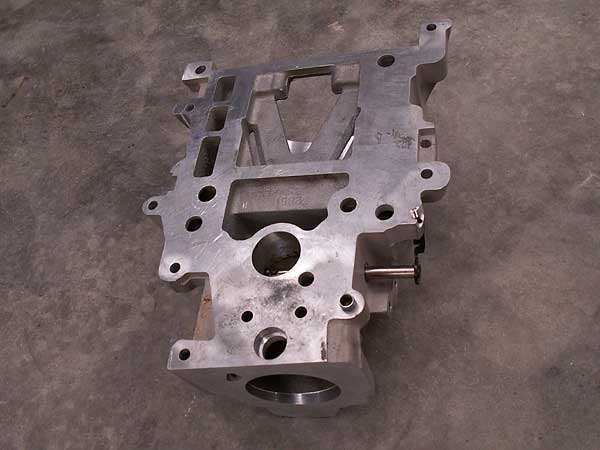
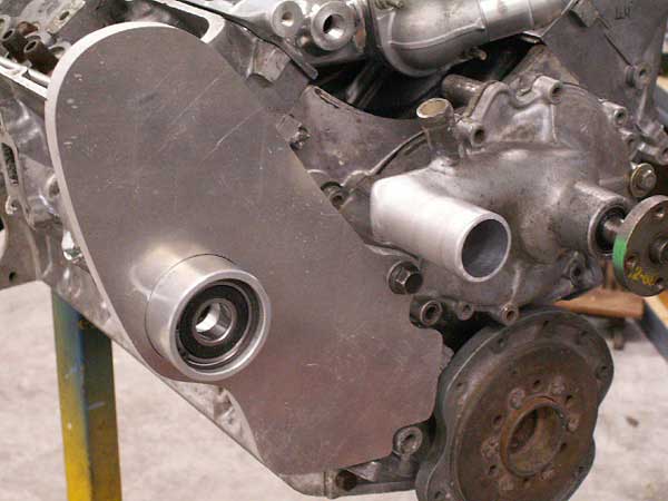
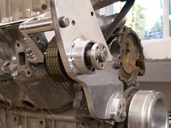
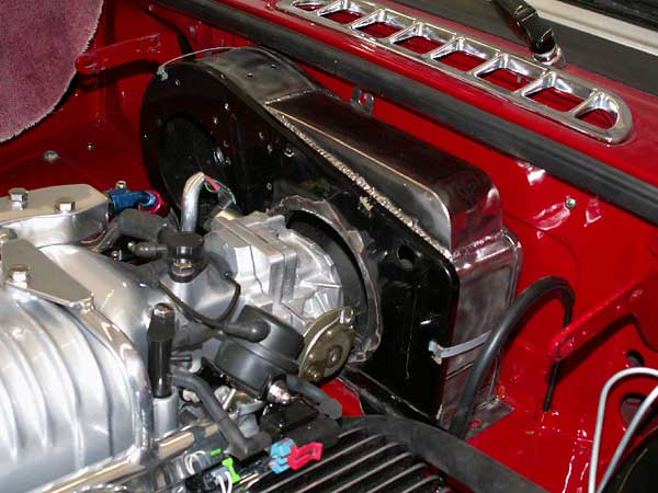
Custom Blower Drive System
��
Because I wanted to keep things compact (for a clean look), the blower drive �
system was a real head-scratcher! The oil pump, water pump, and hood all seemed �
to cause clearance problems. Also, there are a limited number of 8-rib serpentive �
belt lengths available to work with.�
�
I started out making one piece at a time, using cardboard templates to save �
time and aluminum. Most of the belt drive system's frame is made from 1/2" �
aluminum plate. I used a metal lathe to make the idler bearing housing. The �
sealed bearings are press-fit with snap rings to make sure they stay put. �
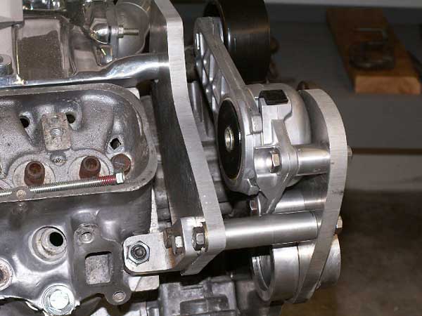
The smaller black pulleys were made by ZZ Performance. The primary drive belt �
tensioner is from a Dodge truck, and the secondary drive belt tensioner is �
from a Ford. I made a round mounting bracket to house the primary tensioner. �
This allowed the tensioner to be reverse-mounted for additional clearance �
at the oil and water pumps. �
| �
Enjoying this article? Our magazine is funded through the generous support of readers like you! � To contribute to our operating budget, please click here and follow the instructions. � (Suggested contribution is twenty bucks per year. Feel free to give more!)� |
�
�
�
Blower drive system: lathe-turned idler bearing housing.
�
�
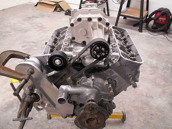
The water pump inlet had to be cut-off and rebuilt with a ninety-degree elbow.
�
�
The Ford secondary drive belt tensioner ("idler pulley") in place.
�
�
The thermostat water neck is has been extended to provide belt/pulley clearance.
�
Less obviously, the distributor has been displaced. Actually, an old distributor has
�
been cut-down to serve as an oil pump drive. (Buick 215 engines had cam-driven oil
�
pumps.) A Ford EDIS ignition system makes the distributor obsolete.
�
�
These mounting flanges allow use of a variety of "bolt-on" ZZ Performance pulleys for drive ratio changes, if desired.�
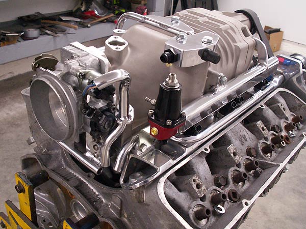
EFI Fuel Rail
��
Here are some pictures of the fuel rails, main pressure regulator, and remote fuel cell. �
�
In order to improve low speed driveability, I recently installed a Vortech Fuel �
Management Unit (FMU). An FMU is a secondary fuel regulator that installs in series �
with the main regulator on the return line to the tank. The FMU is triggered by a �
pneumatic signal from the supercharger. I selected an 8:1 ratio unit. In other words, �
my FMU increases fuel pressure 8 pounds per square inch for every 1 pound of �
boost. (The FMU can be re-calibrated for 3:1 through 12:1 ratios.) �
�
Why is an FMU desireable? In my case, the 21lb injectors are correctly sized for �
engine demand under full boost. However they're a little large for idle or low �
speeds, causing very short duration fuel pulse's at low load conditions. The FMU �
allows me to adjust fuel pressure lower (to 28-30 lbs at idle) and still have high �
fuel pressure under boost. The lower fuel pressure at idle or low engine loads �
allows longer fuel pulses for improved low speed driveability and fuel mileage!�
�
�
Ross Machine Racing extruded aluminum fuel rail stock was used to plumb fuel to the injectors.
�
�
The fuel injectors are 21lb Delphi II units, nominally from a 4.8-5.3L GM pickup truck.
�
I selected the Delphi units for their relatively small external size, which allowed them
�
to fit neatly alongside the blower housing.
�
�
The main fuel pressure regulator is an Aeromotive unit that is adjustable and boost referencing.�
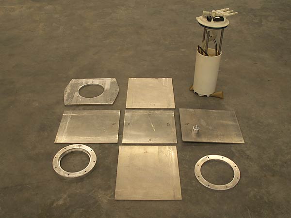
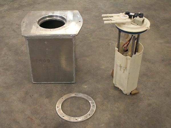
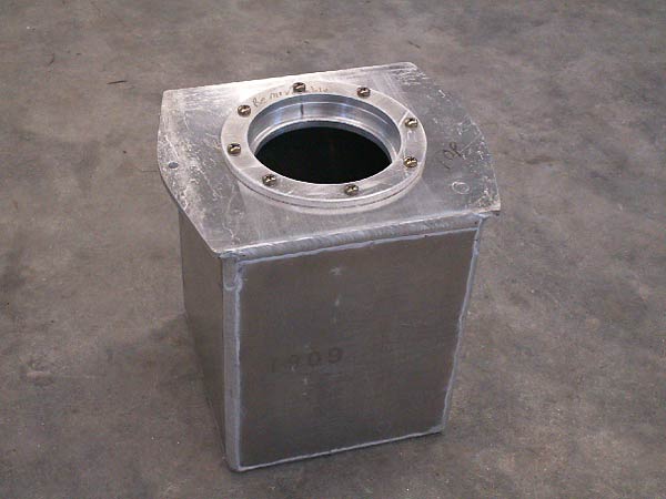
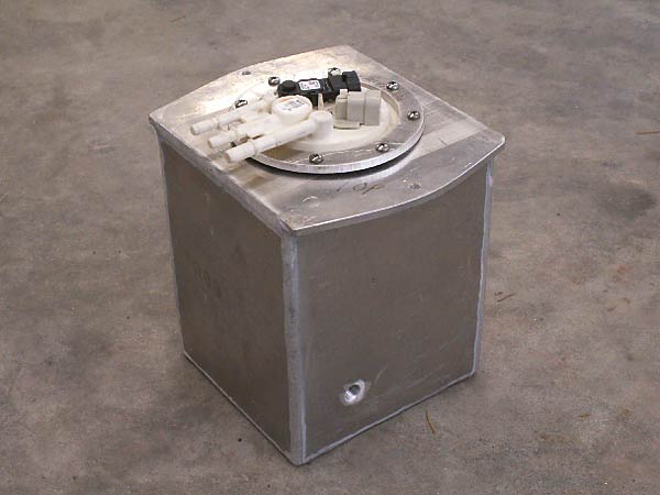
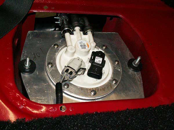
Fabricated Auxiliary Fuel Tank
��
The auxiliary fuel cell contains a slightly-shortened, late-model Chevy Astro �
high-pressure fuel pump that supplies the engine's requirements. Fuel is pumped �
from the main tank to the auxiliary fuel cell by a 72 gph low pressure pump. Excess �
fuel is cycled back from the fuel cell to the main tank via a return line. This keeps �
the cell full at all times. �
�
The auxiliary fuel cell is slightly larger then one of the MGBs original 6-volt batteries. I �
designed it to is mount in the passenger-side battery compartment. (Editor's note: on �
MGBs, there are two battery boxes suspended behind the driver and passenger seats �
respectively.) A "Group 26" 12-volt battery is mounted in the driver-side location. �
�
�
�
�
�
�
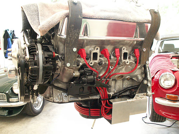
Ford EDIS (Electronic Distributorless Ignition System) Mechanical Parts
��
My Ford Electronic Distributorless Ignition System came off of a 1996 Crown Victoria �
with a 4.6L V8. �
�
EDIS is a type of capacitive discharge ignition which operates on the "wasted spark" �
principle (which briefly means that it fires two cylinders at once, but only one of �
the two sparks matters.) Base ignition timing is determined by a Hall Effect sensor �
situated to detect the passing "teeth" on a crank mounted trigger wheel. �
�
�
I selected an ignition pick-up coil from a parts catalog by looking for one with conveniently
�
oriented mounting tabs. The one I selected is nominally for a Ford Escort, although pretty much
�
any Ford pick-up coil could be made to work. (They all provide a similar signal.)
�
�
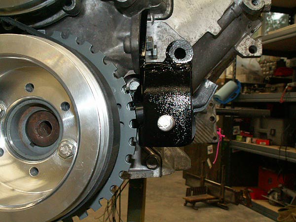
I ordered the trigger wheel from "www.triggerwheels.com". They offer trigger wheels in several
�
diameters. This one is a 7.25" unit that I machined down to 7.125" to clear the timing cover.
�
A also enlarged the center hole so it'd fit the back side of the Buick 215 harmonic balancer.
�
(There are 36 tooth positions on the trigger wheel, except one tooth is deliberatly missing so
�
the system can identify both the crank position angle and the engine speed very accurately.)
�
�
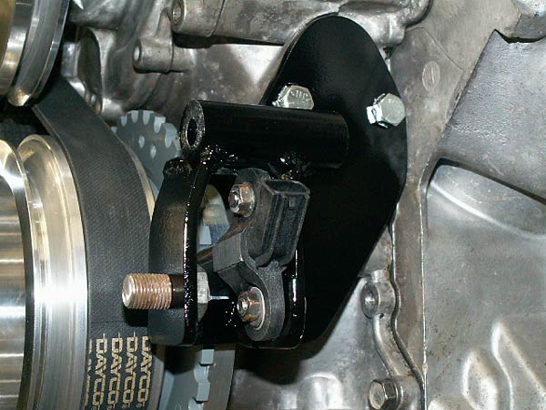
I made a mounting bracket for the primary coil packs, and mounted them to the side of the oil
�
pan. A layer of header wrap between the pan and coils shields them from heat. An aluminum
�
cover helps protect the coils from road debris. (Also, in this photo you can see a torque
�
arm set-up that attaches to the crossmember bolts and limits rotation of the engine.)
�
�
Aluminum billet pulleys for crankshaft and water pump were made to my specs by Peterzelka Brothers.
�
�
EDIS and MegaSquirt Electronic Controllers
��
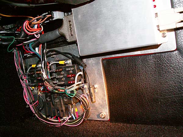
The ignition's electronic control module is mounted to a "main electrical center" �
plate, which is located inside the car on the passinger-side kick panel. The �
MegaSquirt electronic fuel injection system controller, voltage regulator, �
relays and an auxiliary fuse panel are also mounted to this plate.�
�
There are only two short leads between the MegaSquirt controller and the EDIS �
controller, but they're both very important. The fuel injection system gets engine �
speed information from the ignition controller, and based on engine speed and other �
factors it communicates required ignition timing advance back. Ignition advance �
"curves" are stored in the MegaSquirt controller, not the ignition controller! �
(Incidentally, I found them remarkably easy to tune.) �
�
In Ford terminology, the signal wire from the EDIS module to the MegaSquirt system �
is known as the "Profile Ignition Pickup" (PIP). You can think of it as an engine �
speed or "tachometer" output. The MegaSquirt controller uses the PIP signal, the �
Manifold Absolute Pressure (MAP) sensor signal (which, very much like vacuum, is an �
indicator of engine load), and a user-programmed table to determine required �
timing advance. The engine won't run if the PIP signal is lost. (For one thing, the �
fuel injection system will assume the engine has stopped, and cease pumping gas.)�
�
The second signal wire is used by the fuel injection system to communicate �
required ignition advance back to the ignition controller. In Ford terminology, it's �
known as the "Spark Angle Word" (SAW) wire. When the SAW wire is disconnected, the �
ignition system reverts to base timing... almost analogous to disconnecting �
a conventional distributor's vacuum advance hose. The base timing is determined by �
the physical angle between the crank sensor and the missing tooth on the trigger �
wheel. (I installed an inline fuse in the SAW wire to make it more convenient to �
verify base timing with a timing light.) Nominally base timing for the EDIS system �
is 10° before TDC.�
�
�
MegaSquirt is the large silver box on the right, and the EDIS module is just to the left of it.
�
The two black cables with plug-in connectors are for hooking-up an LC-1 wide-band oxygen sensor
�
controller to a laptop computer. O2 sensor data can also be viewed through the MegaSquirt screen.
�
The white cord (in the top right corner) is for connecting MegaSquirt to a laptop computer.
�
Normally a a carpeted panel covers this all up...
�
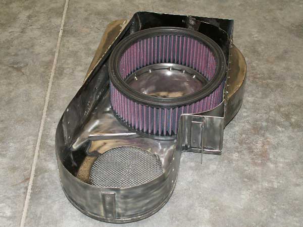
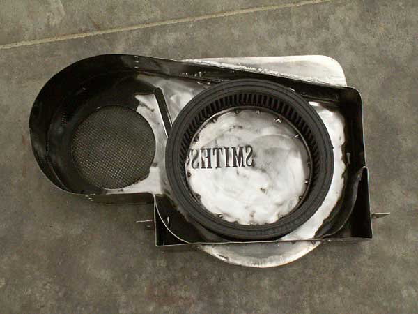
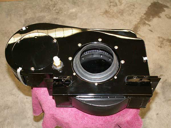
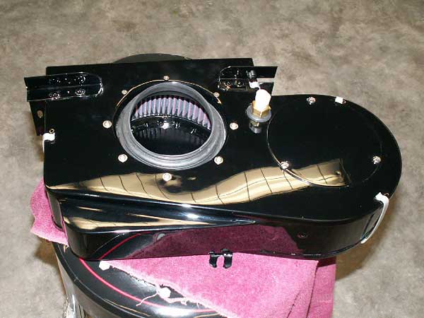
Air Filter Housing (For cowl-induction... made from an old Smith's heater box!)
�� The heater box was added onto above and below, to allow airflow around the the 8" � diameter K&N filter. �
��
�
�
�
�
The rubber coupling between the air box and throttle body was made from a plumbing roof seal!
�
�
�
Installation in the MGB
��
�
�
�

�
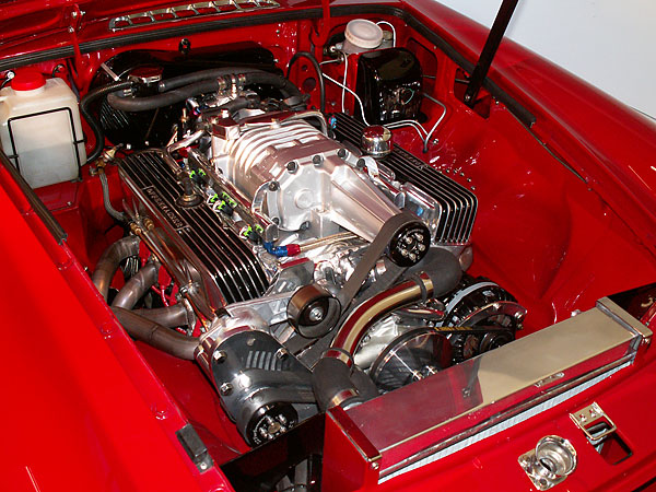
The new supercharger would fit under an unmodified hood. The GTO-style scoop came earlier...
�
�
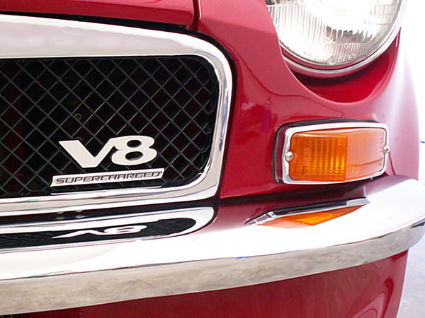
The finishing touch: a "Supercharged" badge from a Chevy Cobalt SS�
�
Disclaimer: This page was researched and written by Bill Jacobson. Views expressed �
are those of the author, and are provided without warrantee or guarantee. Apply at your �
own risk.�
�
Photos by Bill Jacobson for The British V8 Newsletter. All rights reserved.�