�
 �
�
�
�
�
�
�
�
�
�
�
� �
� by: Kelly Stevenson�
� If you're interested in installing an "electronically fuel-injected" (EFI) small block � Ford V8 engine in an MGB, the first decision you'll make is probably whether to start � with a complete donor car, a salvage yard engine, or an already built "crate" engine. � In deciding between potential donor cars, you'll probably focus on '88-'95 Ford Mustangs, � Ford Explorers and Mercury Mountaineers. �
� Many companies build (or remanufacture) Ford engines and sell them as crate engines. � Ford Racing also has crate motors for sale. Horsepower ratings on crate engines appear � to be a marketing fiction. At best, they assume optimized conditions. Generally the � Mustang guys experience only about 260 rear wheel horsepower from their "345hp" rated � Crate engines. Furthermore, many crate engines are sold in "long block" form, which � means they don't include the fuel injection system. This article is specifically � concerned with OEM EFI. �
�
�
�
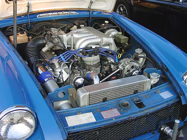
Ford 5.0L EFI Installation in an MGB
� as published in British V8 Newsletter, Volume XIV Issue 3, December 2006�� by: Kelly Stevenson�
� If you're interested in installing an "electronically fuel-injected" (EFI) small block � Ford V8 engine in an MGB, the first decision you'll make is probably whether to start � with a complete donor car, a salvage yard engine, or an already built "crate" engine. � In deciding between potential donor cars, you'll probably focus on '88-'95 Ford Mustangs, � Ford Explorers and Mercury Mountaineers. �
� Many companies build (or remanufacture) Ford engines and sell them as crate engines. � Ford Racing also has crate motors for sale. Horsepower ratings on crate engines appear � to be a marketing fiction. At best, they assume optimized conditions. Generally the � Mustang guys experience only about 260 rear wheel horsepower from their "345hp" rated � Crate engines. Furthermore, many crate engines are sold in "long block" form, which � means they don't include the fuel injection system. This article is specifically � concerned with OEM EFI. �

�
In comparing Ford-OEM EFI systems, one of the first things to note is that Ford used �
two different sensor technologies to measure the amount of air entering the engine. �
The "engine control module" (ECM) must know how much air is entering so that it can �
provide the appropriate matching amount of fuel. Furthermore, the fuel map is �
programmed to be different for cars with different specifications. (For example, �
manual transmission cars may typically be programmed to idle at a slightly higher �
speed than automatic transmission cars.) �
� The two basic sensor technologies to choose between are "speed density" and "mass air". � The speed density system came first (generally around model years '85-'88), and it's � adequate. Speed density systems rely heavily on manifold air pressure (MAP) sensors as � a further input to the ECM in order to estimate engine load. Mass air systems (from � about model years '89-'93) use a hot-wire sensor to actually measure the air flow � entering the throttle body. (Passing air cools the element, which changes its electrical � resistance.) Instead of a MAP sensor, they use a barometric air pressure (BAP) sensor.� They also use two oxygen sensors, an air charge temperature (ACT) sensor, an� engine coolant temperature (ECT) sensor, and a throttle position (TPS) sensor. Don't� let all these sensors intimidate you! Their electrical connections are all different � so they can't be crossed up. The two important things you will want to note are: (1) that � none of the electronic parts of speed density systems are interchangable with the later� mass air system parts, and (2) the mass air systems are much more "tune-able". In fact, � the mass air systems are preferred because they're actually self tuning: their ECM has � the ability to modify or "learn" changes as they occur and to adapt to them. (For � example, the mass-air ECM can adapt better to changes in altitude or fuel quality.)�
��
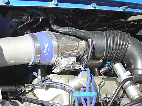
� MAF sensor (PMAS brand) and cold air intake tube.� �
� The ECM that Ford used on their mass air sensor EFI systems is known as an "EEC-IV" � module. (The acronym stands for "Ford Electronic Engine Control version Four".) � All EEC-IV ECM's are NOT the same. The programming is different, based on vehicle specs. �
� If you start with a donor car, the ECM, the main wiring harness, auxiliary wiring, and � all the various and sundry small parts needed are all included! The ECM that came with � my donor 1993 Mustang LX is an "A9L" EEC-IV, and I have been happy with its programming. �
� If the vehicle wiring is damaged or missing, purchase Ford factory replacement harnesses. � (Note: part number M12071-C302 is the main engine harness for a '93 Mustang LX). You can � also purchase a mass air harness package complete with sensors. (For more information on � wiring, the Mustang online bulletin boards are a valuable resource. Also, the Ford Fuel � Injection Manual is ISM# 12071-302 and is strongly recommended. You can order a printed � copy from Ford, or download a copy from various online sources.) �
��
 �
�
�
� In addition to the main engine wiring harness, there are usually three smaller � harnesses: one for the fuel injectors, one for the alternator, and one for the "heated � exhaust gas oxygen" (HEGO) sensor. If you have a donor car, these should all be there. �
� We removed tape from the main Ford harness and relocated the coil connector. The coil � is now mounted to the front of the left head. The HEGO connector, positive power wires � (solenoid) & ECM grounds are all on the passenger-side of the car to ease connection to � the MGB harness. We chose to plug the Ford temperature sender hole and drill the Ford � thermostat housing water outlet for mounting an MGB sender. The MGB sender is an odd � size (5/8"X 18). This change required that the temperature wire be removed from the � injector harness and routed up the right side of the lower manifold. �
� We removed the MGB front fan relay and stripped the white & brown wires out since � they are needed to power the Ford system. (White is "ignition switched power" and brown is � "battery power".) The start or "crank" wire came from the OEM MGB starter relay and � connects to the big Ford relay solenoid. The dedicated ground cable from the battery � also mounts to the ECM ground just below the Ford relay. (Note: reliable grounds tend � to be extremely important on an EFI engine!) �
� The MGB ignition light is connected to the Ford wire that performs the same function � (noted in the wiring manual) so the dash charging light functions also. �
� We made a "check engine" light from an orange LED (Speedway Motors 911-31050-orange). � This was mounted in the radio console on the left-hand side (visible to driver only). �
� We chose a modified "March Performance" pulley system to drive the alternator and water � pump. The alternator was moved to the driver-side of the engine bay, and its top mounting � ear was cut and re-welded with the housing clocked to allow maximum space for coil and � valve cover. (A local alternator repair shop handled this modification.) �
��
�
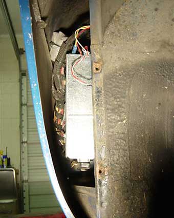
We chose to mount the Ford ECM in the recess behind the passenger-side front tire �
(covered by the bolted-in "splash panel"). We made a sheet metal enclosure, that's �
open at the bottom, to further protect the ECM. Be sure to reverse the mounting �
bracket to the outside wall since the original mounted on the inside of the car. This �
will allow the wiring to enter from the front. The Ford EFI Manual gives the procedure �
for cutting the oblong hole to fit the grommet on the main wiring harness. This manual �
is available online, or comes with the OEM replacement wiring harness.�
��
�
� The Ford manual further details the color codes of wires that need connection to the � MGB wiring. On the transmission, the wiring needs to be connected to the "vehicle speed � sensor" (VSS) and reverse-light switch, and the neutral safety switch. The VSS is hooked � to the corresponding wires running to the ECM while the back-up-light switch is wired � direct to the MGB wiring for the same circuit. (The neutral switch is not needed for � operation, but will cause the ECM to record code "67" every time you pull codes from � ECM.) �
� The "barometric air pressure" (BAP) sensor easily mounts just to the left of the � heater housing. The main harnesses are routed behind the washer bracket. �
� The gas vapor canister and purge valve are mounted just behind the OEM washer reservoir � bracket.�
��
�
What fuel tank modifications were required for EFI? Modern EFI systems incorporate �
a high pressure supply line and also a lower pressure return line that takes excess fuel back �
to the fuel tank. We decided to use the original (late-model) MGB fuel level sender's integral �
fuel pick-up tube for "return". To make this work out, we modified the pick-up so that it �
turned away from the tank's sump to eliminate cavitation. With the fuel tank removed from the �
car, we drilled a hole in the passenger-side bottom corner of the tank (i.e. under the filler �
spout) and we bent a 3/8" steel line so that it laid in the lowest part of the sump with a �
filter sock attached. (Note: with the fuel-lever sender removed we could see what we were �
doing inside the tank.) We fabricated a flanged plug with internal pipe thread to mount a �
barbed 3/8" fitting outside and we mounted the steel 3/8" line to the inside of this plug. �
We then silver-soldered the 3/8" line into the plug and drilled a hole adequate to slip the �
plug, line & filter into the tank. The flanged plug & line was silver soldered to the tank �
and is leak free.�
�
�
�
� The two basic sensor technologies to choose between are "speed density" and "mass air". � The speed density system came first (generally around model years '85-'88), and it's � adequate. Speed density systems rely heavily on manifold air pressure (MAP) sensors as � a further input to the ECM in order to estimate engine load. Mass air systems (from � about model years '89-'93) use a hot-wire sensor to actually measure the air flow � entering the throttle body. (Passing air cools the element, which changes its electrical � resistance.) Instead of a MAP sensor, they use a barometric air pressure (BAP) sensor.� They also use two oxygen sensors, an air charge temperature (ACT) sensor, an� engine coolant temperature (ECT) sensor, and a throttle position (TPS) sensor. Don't� let all these sensors intimidate you! Their electrical connections are all different � so they can't be crossed up. The two important things you will want to note are: (1) that � none of the electronic parts of speed density systems are interchangable with the later� mass air system parts, and (2) the mass air systems are much more "tune-able". In fact, � the mass air systems are preferred because they're actually self tuning: their ECM has � the ability to modify or "learn" changes as they occur and to adapt to them. (For � example, the mass-air ECM can adapt better to changes in altitude or fuel quality.)�
�
� MAF sensor (PMAS brand) and cold air intake tube.�
� The ECM that Ford used on their mass air sensor EFI systems is known as an "EEC-IV" � module. (The acronym stands for "Ford Electronic Engine Control version Four".) � All EEC-IV ECM's are NOT the same. The programming is different, based on vehicle specs. �
� If you start with a donor car, the ECM, the main wiring harness, auxiliary wiring, and � all the various and sundry small parts needed are all included! The ECM that came with � my donor 1993 Mustang LX is an "A9L" EEC-IV, and I have been happy with its programming. �
� If the vehicle wiring is damaged or missing, purchase Ford factory replacement harnesses. � (Note: part number M12071-C302 is the main engine harness for a '93 Mustang LX). You can � also purchase a mass air harness package complete with sensors. (For more information on � wiring, the Mustang online bulletin boards are a valuable resource. Also, the Ford Fuel � Injection Manual is ISM# 12071-302 and is strongly recommended. You can order a printed � copy from Ford, or download a copy from various online sources.) �
�
�
� In addition to the main engine wiring harness, there are usually three smaller � harnesses: one for the fuel injectors, one for the alternator, and one for the "heated � exhaust gas oxygen" (HEGO) sensor. If you have a donor car, these should all be there. �
� We removed tape from the main Ford harness and relocated the coil connector. The coil � is now mounted to the front of the left head. The HEGO connector, positive power wires � (solenoid) & ECM grounds are all on the passenger-side of the car to ease connection to � the MGB harness. We chose to plug the Ford temperature sender hole and drill the Ford � thermostat housing water outlet for mounting an MGB sender. The MGB sender is an odd � size (5/8"X 18). This change required that the temperature wire be removed from the � injector harness and routed up the right side of the lower manifold. �
� We removed the MGB front fan relay and stripped the white & brown wires out since � they are needed to power the Ford system. (White is "ignition switched power" and brown is � "battery power".) The start or "crank" wire came from the OEM MGB starter relay and � connects to the big Ford relay solenoid. The dedicated ground cable from the battery � also mounts to the ECM ground just below the Ford relay. (Note: reliable grounds tend � to be extremely important on an EFI engine!) �
� The MGB ignition light is connected to the Ford wire that performs the same function � (noted in the wiring manual) so the dash charging light functions also. �
� We made a "check engine" light from an orange LED (Speedway Motors 911-31050-orange). � This was mounted in the radio console on the left-hand side (visible to driver only). �
� We chose a modified "March Performance" pulley system to drive the alternator and water � pump. The alternator was moved to the driver-side of the engine bay, and its top mounting � ear was cut and re-welded with the housing clocked to allow maximum space for coil and � valve cover. (A local alternator repair shop handled this modification.) �
�
 | �
 | �
| �
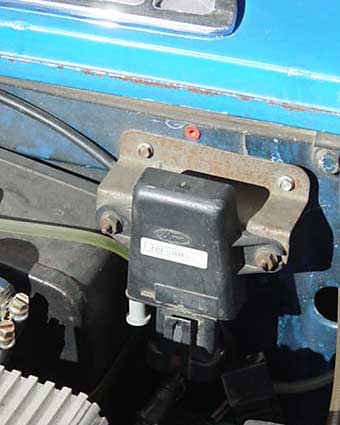
ECM, mounted behind passenger-side wheel splash panel | �
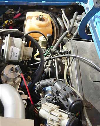
� BAP sensor near driver-side hood hinge | �
 | �
 | �
| �
Engine harness connectors | �
�
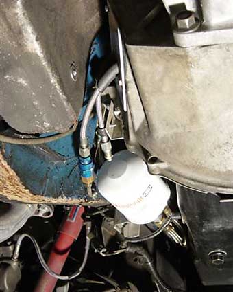
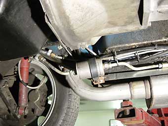
Remote oil filter at left rear and HTOB lines | �
�
| �
Enjoying this article? Our magazine is funded through the generous support of readers like you! � To contribute to our operating budget, please click here and follow the instructions. � (Suggested contribution is twenty bucks per year. Feel free to give more!)� |
� The Ford manual further details the color codes of wires that need connection to the � MGB wiring. On the transmission, the wiring needs to be connected to the "vehicle speed � sensor" (VSS) and reverse-light switch, and the neutral safety switch. The VSS is hooked � to the corresponding wires running to the ECM while the back-up-light switch is wired � direct to the MGB wiring for the same circuit. (The neutral switch is not needed for � operation, but will cause the ECM to record code "67" every time you pull codes from � ECM.) �
� The "barometric air pressure" (BAP) sensor easily mounts just to the left of the � heater housing. The main harnesses are routed behind the washer bracket. �
� The gas vapor canister and purge valve are mounted just behind the OEM washer reservoir � bracket.�
�
 | �
 | �
| �
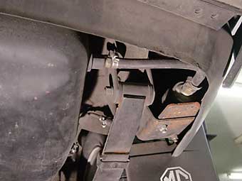
Driver-side of fuel tank, and fuel pump mounting | �
�
Fuel filter & EFI line connections to engine & return line to old MGB line | �
�
�
On our installation, most of the supply (or "pressure side") fuel line is 5/16" steel tubing �
(from Summit), but I would suggest you try aluminum for ease of fabrication. The one place �
where we used 3/8" steel line was in the immediate vicinity of the fuel filter. The 3/8" �
steel fuel line was sourced from a Chevrolet truck in the salvage yard. We preferred the �
Chevrolet truck fuel filter's threaded nuts (for 3/8" line) over slip-lock connectors. �
Our trick was to slip the end of 5/16" steel line inside short pieces of 3/8" line, and �
then silver solder them together. (3/8" line can easily be double flared for any unions.) �
We used a little flex line too: from the fuel tank to the pump. Regular fuel hose isn't up �
to the job, so make sure to get "EFI" rated hose. The OEM fuel rails were used along with the �
OEM fittings. (They required some bending to re-use). That's it for the supply side! As �
mentioned above, the MGB's original gas line was used for the return side. �
� Fuel pump: fabricated mounting bracket for MSD Electric Pump part number 2225 ($95 on eBay). � This pump is plumbed for 3/8" inlet and 5/16" outlet. The mount was welded to the right � rear factory tow bracket just behind the tire up inside the quarter-panel. The pump was � bolted to another bracket to allow it to be removed easily and serviced if needed. It � was powered from a relay in the trunk activated by the MGB fuel pump power wire. A � separate fused wire runs to the battery and hooks directly to the relay. The MGB under-dash � "upset switch" was eliminated and a Mustang inertia switch was wired-in instead. �
� Induction: a "CAI" (cold air intake) was made from a 3" diameter piece of tubing from � a muffler shop. The tubing is mated to K&N Filter (part number RF1030, approximately � $75). It was routed through the passenger-side radiator bracket and is secured to the � slam panel in front and centered. A bell-shaped silicone hose (i.e. 4" X 3" transition) � connects the tubing to the mass-air sensor, which in turn is connected to the Ford molded � rubber elbow. �
��
�
�
�
� Fuel pump: fabricated mounting bracket for MSD Electric Pump part number 2225 ($95 on eBay). � This pump is plumbed for 3/8" inlet and 5/16" outlet. The mount was welded to the right � rear factory tow bracket just behind the tire up inside the quarter-panel. The pump was � bolted to another bracket to allow it to be removed easily and serviced if needed. It � was powered from a relay in the trunk activated by the MGB fuel pump power wire. A � separate fused wire runs to the battery and hooks directly to the relay. The MGB under-dash � "upset switch" was eliminated and a Mustang inertia switch was wired-in instead. �
� Induction: a "CAI" (cold air intake) was made from a 3" diameter piece of tubing from � a muffler shop. The tubing is mated to K&N Filter (part number RF1030, approximately � $75). It was routed through the passenger-side radiator bracket and is secured to the � slam panel in front and centered. A bell-shaped silicone hose (i.e. 4" X 3" transition) � connects the tubing to the mass-air sensor, which in turn is connected to the Ford molded � rubber elbow. �
�
 | �
 | �
| �
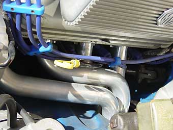
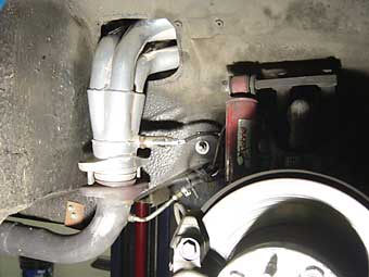
Driver-side header | �
�
Passenger-side header & oxygen sensor | �
�
Fabricating headers was the most time consuming and skill-intensive part of our engine �
swap. We purchased a Hedman header kit or "box of bends" for the Ford 5.0 (with 1 5/8" �
tubing). It had both left and right flanges and enough angles to complete our set with �
some left over. We also used 3" Flowmaster ball-flange collectors from Summit. The end �
results are good. The headers fit and work, plus we can change all spark plugs without �
any difficulty - but it wasn't cheap! Our total cost (not including labor) was in excess �
of $800 with more than 55 hours of our own fabrication work. �
� There are now cost effective headers specifically made for Ford-MGB engine conversions, � in both thru-the-fender and block-hugger configurations, and you'll want to consider � them. �
� Whatever headers you select, the EFI ECM requires oxygen sensors (two: one per cylinder � bank) in the exhaust stream. We welded O2 sensor bungs onto the headers after some careful � measuring to make sure the sensors wouldn't be damaged by the wheels at full wheel lock. �
� Finally, we sent our completed headers to Jet-Hot for application of their ceramic coating � which provides durable corrosion protection and also performance benefits (because it � helps keep heat inside the pipes). They provided very quick service. Suggestion: prior to � coating, have the flanges trued or milled flat to prevent leaks later. �
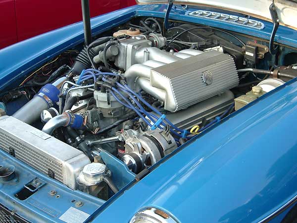
� Ford EFI typically sits taller than a carburetor. A cowl type hood scoop or MGB-style � bulged hood will likely be required, unless you're prepared to fabricate a special � low-profile "spider" type intake manifold. The MGC-style hood I selected is fiberglass, � and was provided by "Team Liebre" in Pennsylvania. (Editor's note: this model of hand-laid � fiberglass MGC-style hood is no longer available from Team Liebre, but it is available � from Tim Nagy at morSpeed � Performance Products.) �
� Engine Specifications:
� 5.0 EFI Mustang, X-303 FPP heads, GT-40 Ford intake, 24lb. Ford injectors (in lieu of � stock 19lb injectors), 65mm throttle body, PMAS 75mm mass air sensor, Comp Cam � XE-264-HR-14 roller cam (could use more cam, but torque is great!), Ford Explorer timing � cover, water pump, and harmonic balancer. Baseline dynamometer test: 266 RWHP & � 298 Torque@ 4800rpm.�
� Disclaimer: This page was researched and written by Kelly Stevenson. Views expressed � are those of the author, and are provided without warrantee or guarantee. Apply at your � own risk.�
�
�
� There are now cost effective headers specifically made for Ford-MGB engine conversions, � in both thru-the-fender and block-hugger configurations, and you'll want to consider � them. �
� Whatever headers you select, the EFI ECM requires oxygen sensors (two: one per cylinder � bank) in the exhaust stream. We welded O2 sensor bungs onto the headers after some careful � measuring to make sure the sensors wouldn't be damaged by the wheels at full wheel lock. �
� Finally, we sent our completed headers to Jet-Hot for application of their ceramic coating � which provides durable corrosion protection and also performance benefits (because it � helps keep heat inside the pipes). They provided very quick service. Suggestion: prior to � coating, have the flanges trued or milled flat to prevent leaks later. �
� Ford EFI typically sits taller than a carburetor. A cowl type hood scoop or MGB-style � bulged hood will likely be required, unless you're prepared to fabricate a special � low-profile "spider" type intake manifold. The MGC-style hood I selected is fiberglass, � and was provided by "Team Liebre" in Pennsylvania. (Editor's note: this model of hand-laid � fiberglass MGC-style hood is no longer available from Team Liebre, but it is available � from Tim Nagy at morSpeed � Performance Products.) �
� Engine Specifications:
� 5.0 EFI Mustang, X-303 FPP heads, GT-40 Ford intake, 24lb. Ford injectors (in lieu of � stock 19lb injectors), 65mm throttle body, PMAS 75mm mass air sensor, Comp Cam � XE-264-HR-14 roller cam (could use more cam, but torque is great!), Ford Explorer timing � cover, water pump, and harmonic balancer. Baseline dynamometer test: 266 RWHP & � 298 Torque@ 4800rpm.�
� Disclaimer: This page was researched and written by Kelly Stevenson. Views expressed � are those of the author, and are provided without warrantee or guarantee. Apply at your � own risk.�
