�
 �
�
�
�
�
�
�
�
�
�
�
� (This article appeared in Volume IX Issue 3, September 2001.)�
� � Dan Lagrou of D&D Fabrications has been building high performance 215 engines for over 25 years, including many dozens of aluminum V8 stroker motors. With the advent in 1994 of a new Rover block with cross-bolted mains and a 3.7" bore, Dan developed a recipe for a 294 inch (4.8L) stroker motor which weighs in dry at a flyweight 340 pounds! The stroker incorporates an esoteric blend of parts from the Buick, Rover, Ford and Chevrolet parts bins, but the combination is well proven and all of the parts are readily available. The primary components are a late Rover block mated to a 1964 - 67 Buick 300crankshaft and '64 Buick 300 heads. For stuffing into an MG, Triumph, Healey, or other British iron, the Rover stroker engine cannot be beat.�
� Below are Dan's recommendations for a "basic" stroker which will put out plenty of torque and live a long time. These are listed in the recipe below as "mandatory" items. To go to the nth degree of preparation and gain some longevity under demanding conditions, (and probably a few more horses) several "insurance" options are noted.�
��
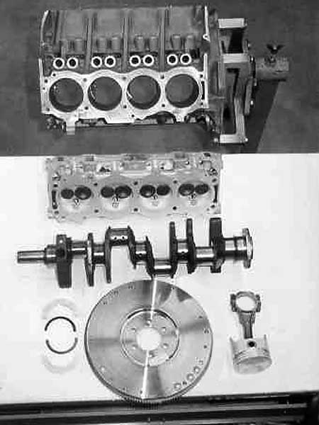
� Major components of the Rover/BOP stroker engine� �
�
�
Recipe for an Affordable Stroker V8
� By: Kurt Schley �� (This article appeared in Volume IX Issue 3, September 2001.)�
� � Dan Lagrou of D&D Fabrications has been building high performance 215 engines for over 25 years, including many dozens of aluminum V8 stroker motors. With the advent in 1994 of a new Rover block with cross-bolted mains and a 3.7" bore, Dan developed a recipe for a 294 inch (4.8L) stroker motor which weighs in dry at a flyweight 340 pounds! The stroker incorporates an esoteric blend of parts from the Buick, Rover, Ford and Chevrolet parts bins, but the combination is well proven and all of the parts are readily available. The primary components are a late Rover block mated to a 1964 - 67 Buick 300crankshaft and '64 Buick 300 heads. For stuffing into an MG, Triumph, Healey, or other British iron, the Rover stroker engine cannot be beat.�
� Below are Dan's recommendations for a "basic" stroker which will put out plenty of torque and live a long time. These are listed in the recipe below as "mandatory" items. To go to the nth degree of preparation and gain some longevity under demanding conditions, (and probably a few more horses) several "insurance" options are noted.�
�
� Major components of the Rover/BOP stroker engine�
�
��
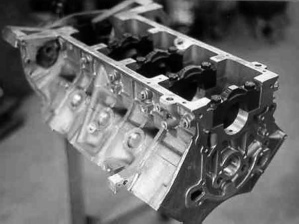
� Rover 4.0/4.6 cross-bolted main engine block� �
� For some reason, undersize main bearings are not available from Rover or any aftermarket sources for the new aluminum V-8 blocks. Apparently, Rover feels that if a crankshaft requires grinding undersize, it should be replaced outright. If the Buick 300 crankshaft is in good condition and only requires a polish, the stock Rover main bearings can be used. However, if the crankshaft has been ground undersize, Buick 300 undersize bearings are readily available and can be installed in the Rover block. This will require line boring the block's main bearing bores approximately 0.022" to fit the Buick bearing's larger O.D. Dan Lagrou recommends this procedure even with a stock crank journal size in case the crank needs grinding undersize at a later rebuild.�
� Mandatory Operations:�
� (1) Check the cylinder bores for diameter and out-of-round condition. There seems to have been a problem with the cylinders being slightly oval on the 4.0 and 4.6L V-8's. Several rebuilders have reported that they often observe the cylinder not becoming "round" until the boring bar gets out to about +0.007".For this reason, any Rover block should be over-bored 0.010" to 3.710", to insure proper cylinder concentricity. Check and make sure the machine shop will be using torque plates when they bore the block. The cylinder bores can distort a few thousands of an inch when the heads are bolted on. It is counterproductive to carefully machine the block, without torque plates, only to have the cylinders distort during engine assembly. �
� (2) After machining, wash the block thoroughly with hot water and soap. Clean all small bores and oil passages with a plastic brush. Dry with compressed air and oil the cylinder bores immediately.�
� Insurance Operations:�
� (1) Check the block for casting flash and spend a little time with a grinder, smoothing off sharp casting lines and removing flash. Just as with a cast-iron block, fatigue fractures in an aluminum version will always initiate on sharp edges. Pay close attention to the lifter valley; any flash which comes off here will go right into the oil. The really fastidious engine builders will actually polish this area to aid oil drainback.�
� (2) Chase all the threaded bolt holes with a tap, preferably a bottoming tap, to remove crud, and make sure the threads are in good condition. This will help to insure that torque readings during engine assembly are correct. A bottoming tap can be made by grinding off the taper end of a standard tap. (SAE taps work fine in all except the crossbolt threads, which are metric.)�
�
�
�
Engine Block
� In 1994 Rover introduced an improved block for use in all Rover V-8 applications, including the Land and Range Rover SUV's. The new block incorporates added reinforcing webbing, but more importantly, it also carries cast-in bosses for 4-bolt main bearing caps: two vertical bolts per earlier production, plus two horizontal bolts securing each cap from the side and effectively tying the whole lower end securely together. The new block casting carries the number HRC2411 on one side. The four bolt bosses are in place, but not drilled for the current 3.9 or a now defunct 4.2L engines, nor are the necessary larger main bearing caps provided. The block we are most interested in is for the 4.0L and 4.6L engines. These engines do have 4-bolt mains with the corresponding larger caps. Flexing of the lower end has been completely eliminated and the lower end is now practically bulletproof.��
� Rover 4.0/4.6 cross-bolted main engine block�
� For some reason, undersize main bearings are not available from Rover or any aftermarket sources for the new aluminum V-8 blocks. Apparently, Rover feels that if a crankshaft requires grinding undersize, it should be replaced outright. If the Buick 300 crankshaft is in good condition and only requires a polish, the stock Rover main bearings can be used. However, if the crankshaft has been ground undersize, Buick 300 undersize bearings are readily available and can be installed in the Rover block. This will require line boring the block's main bearing bores approximately 0.022" to fit the Buick bearing's larger O.D. Dan Lagrou recommends this procedure even with a stock crank journal size in case the crank needs grinding undersize at a later rebuild.�
� Mandatory Operations:�
� (1) Check the cylinder bores for diameter and out-of-round condition. There seems to have been a problem with the cylinders being slightly oval on the 4.0 and 4.6L V-8's. Several rebuilders have reported that they often observe the cylinder not becoming "round" until the boring bar gets out to about +0.007".For this reason, any Rover block should be over-bored 0.010" to 3.710", to insure proper cylinder concentricity. Check and make sure the machine shop will be using torque plates when they bore the block. The cylinder bores can distort a few thousands of an inch when the heads are bolted on. It is counterproductive to carefully machine the block, without torque plates, only to have the cylinders distort during engine assembly. �
� (2) After machining, wash the block thoroughly with hot water and soap. Clean all small bores and oil passages with a plastic brush. Dry with compressed air and oil the cylinder bores immediately.�
� Insurance Operations:�
� (1) Check the block for casting flash and spend a little time with a grinder, smoothing off sharp casting lines and removing flash. Just as with a cast-iron block, fatigue fractures in an aluminum version will always initiate on sharp edges. Pay close attention to the lifter valley; any flash which comes off here will go right into the oil. The really fastidious engine builders will actually polish this area to aid oil drainback.�
� (2) Chase all the threaded bolt holes with a tap, preferably a bottoming tap, to remove crud, and make sure the threads are in good condition. This will help to insure that torque readings during engine assembly are correct. A bottoming tap can be made by grinding off the taper end of a standard tap. (SAE taps work fine in all except the crossbolt threads, which are metric.)�
Crankshaft
� The Buick 300 crankshaft was unchanged through all four years of the engine's production. Cast from ArmaSteel (pearlitic malleable iron), it weighs 45.6lbs. This crank has been used successfully for years for stroking the Buick/Olds 215 and the Rover 3.5 and 3.9L engines. However, the 300 crankshaft main bearing journals must to be turned down 0.200" to fit the early aluminum V-8 mains. Though this has rarely been a problem in actual use, for high horsepower or heavy duty applications, reliability would obviously benefit from retaining the full 2.5" diameter main bearing journal. Fortunately, the redesign of the new Rover blocks included opening up the main bearing to match those of the original 300 crank journals.��
�
Mandatory Operations:�
� (1) Magnafluxing - The Buick 300 crankshafts are 35+ years old and the operating history of a particular crank is very seldom known. It is frustrating and expensive to build an engine, only to have it grenade because of a pre-existing crack in the crankshaft. Magnaflux inspection detects even small fractures and surface imperfections by the use of a magnetic powder and an electromagnet. The powder is dusted onto the crankshaft and a magnetic field is set up on the metals surface with the magnet. Cracks and surface flaws interrupt the magnetic field and force the powder to form lines along the imperfection. All competent machine shops can inexpensively perform Magnafluxing of ferrous (iron-based) engine components.�
� (2) With a micrometer, carefully check the main and rod journals for diameter, ovality and taper. Visually check for grooves or scoring, damage to the chamfers at the sides of the journals, and for blue tinting of the journals which indicate overheating. Have the main and /or rod journals machined .010" undersize if necessary and modify the block for undersize Buick 300 main bearings.�
� (3) Check the crank for straightness. This can be done either before any necessary machining or afterward. If done before, the check can be made by installing the crank in a lathe or a jig which holds both ends firmly centered. A dial indicator is placed on the center main bearing journal and the crankshaft slowly rotated. The journal should not indicate more than 0.002" lateral travel.�
� Note: If the crankshaft has been machined or does not require machining, it can be installed into the block, using only the front and rear main bearings and caps. Lubricate the bearings and torque the caps to spec. Place a dial indicator on the center main bearing journal and spin the crankshaft. Again, the indicator should show no more than 0.002" total lateral runout. Any competent machine shop can straighten a bent crankshaft relatively easily.�
� (4) Install a new pilot bushing. If the pilot bushing is worn, the transmission input shaft as well as the clutch friction disc will wobble. This will manifest itself in a chattering clutch, hard shifts, and damage to the transmission. A new pilot bushing is only a couple of bucks and installation takes five minutes. The trick to removing the old bushing is to pack the old bushing full of heavy grease. Place an old transmission input shaft, or any metal rod which fits closely, into the bushing. A few short raps on the rod with a hammer, and the hydraulic action of the grease will ease the bushing from the crank.�
� Insurance Operations:�
� (1) Chamfer the oil passages. �
� (2) Deburr the crankshaft.�
� (3) Chase the threads.�
� (4) Cross drilling.�
�
� As with the crankshaft there are several mandatory operations plus some which, while not being absolutely necessary, can reduce the chance of rod failure.�
� Mandatory Operations:�
� (1) Make sure that if you are removing the rods from a donor engine that each rod and end cap pair is marked so that they are always matched to their original mate.�
� (2) Beadblast the rods to make sure they are absolutely clean.�
� (3) Magnafluxing - Prior to having any work done on the rods, they should be Magnafluxed to check for possible cracks. The machine shop should also check the rods for straightness.�
� (4) Have the small ends reamed to 0.905 - 0.907", then honed to 0.9100 - 0.9105". Make sure the machinist hones the small end out to its final dimension. Some shops may try to merely ream to the finished size. Reaming is not a precision operation and cannot achieve the precise dimensioning required for proper fit of the wrist pin. The Buick/Olds/Rover all are designed for pressed wrist pins which are held rigidly in the rods and do not ride in a bushing. The small end should have a wrist pin interference clearance of 0.0015 - 0.0020" which will allow the pins to be pressed into position. The edges of the small end should be chamfered or deburred, after honing, to remove sharp edges or burrs which may interfere with pin installation.�
� (5) After undergoing millions of cycles, used connecting rod big ends usually become oval, with the larger diameter parallel with the rod beam. This distortion prevents the con rod bearings from fitting properly and can lead to oil pressure loss, rapid bearing wear or a spun bearing. The rod big ends should be resized by a competent machine shop.�
� The machinist will:
� a) Remove the rod cap and grind some material from the cap face and the rod face.
� b) Reinstall the cap onto the rod and torque the bolts.
� c) Hone the big end to its proper I.D.
� d) Reduce the c/l to c/l distance as little as possible and insure that this distance is kept as consistent as possible from rod to rod. This is a very important criterion that the machinist must meet.�
� Insurance Operations:�
� (1) Polish the rod beams�
� (2) Have the rods shot blasted�
�
��
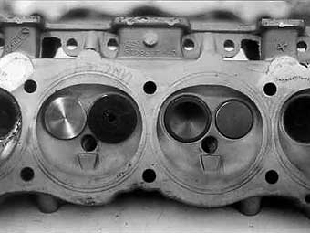
� Stock valves on the right, Pontiac/VW valves on the left� �
� The advantages of the 300 heads for the stroker motor are numerous. First is obviously the light weigh. Secondly, the combustion chambers are dimensioned for the 300's 3.750" bore which works nicely to that of the Rover, particularly after the Rover bore is taken out to 3.710". The 54cc combustion chamber, using a .050" thick composite Rover head gasket, will yield a 10.4:1 compression ratio. �
��
�
� Because aluminum heads dissipate heat quickly, they can tolerate higher compression ratios without detonation.�
� The stock 300 heads will not breathe sufficient air and fuel to keep up with the demands of the stroker engine. Dan's recipe calls for larger valves, mild porting and a few other tweaks to bring the heads up to the performance levels we are seeking. The intake valve is replaced with a 1.720" diameter piece from the 1988 - 92 Pontiac "Iron Duke" 151ci 4-cylinder engine (Federal Mogul p/n V2530). The300 head's exhaust is opened up using Manley P/N 11667-4 Volkswagen 38mm (1.496) stainless steel intake valves. The larger valves will require new seats, such as Precision PC1500-31 (exhaust) and PC1750-39 (intake), which any competent machine shop can easily install, and the new valves and seats get a three-angle grind. The machine shop will also grind the valve lengths to match the Buick 300 stock length.�
� The guides on the 300 heads are undoubtedly worn and the new valves stem diameters differ from the stock 300's, so the guides must be sleeved. One guide liner option is Ohio P/N 6896H. At the same time, have the machinist cut the tops of the valve guides and install a Perfect Circle style valve stem seal on the intakes only.�
� To assist with gas flow, both the inlet and exhaust port pockets should be opened up to match the valve seat diameters. The face of the boss supporting the valve guide is smoothed and shaped to minimize airflow restriction and the length of the guide cut down. (See Porting the Buick 300 Head, page7). Finally, have the machine shop take a skim pass on the gasket side of the head to insure a flat surface for sealing with the block.�
�
� Buick 215, '62-'63 Buick V-6 and early Rover 3.5L covers are readily available and cheap. There are two slight disadvantages in their use. First is that the original front seals were the archaic rope type, which always required finesse and a measure of luck to achieve a leak free installation. Fortunately, the rope seals can be easily replaced with a D&D Fabrication P/N 45932 one piece rubber seal which installs into the cover without modifications. The second concern is that the degree lines on the cover's cast-in timing boss will not correspond to the timing mark on the Buick 300 harmonic balancer. Again, this is easily rectified: �
� 1) With the crankshaft and front cover installed and the driver's side head off of the block, bring the #1 piston to TDC.�
� 2) Carefully place a mark on the edge of the balancer, aligned with the 0° line on the cover's timing boss.�
� 3) With a hacksaw, cut a groove at the marked location on the balancer. This is the new timing mark. (Filling in the groove with white paint makes timing a little easier in a dark garage.)�
� Rover late 3.5L and early 3.9L covers use modern one-piece rubber front seals. Because of misalignment between the cover timing marks and that on the 300 balancer, the balancer must be remarked as above.�
� Buick 300 covers have two 1/4" diameter holes for the locator dowels which must be opened up to 5/16". They were also of the rope-type seal design, thus requiring the same D&D replacement seal as the 215 and early Rover covers. The timing mark boss is in the correct position. Buick 1964 - 67 V-6 front covers are identical to the Buick 300.�
��
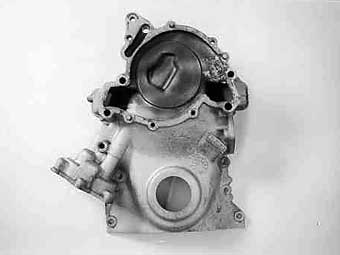
� Buick 300 front cover� �
� Late 3.9L and 4.2L Rover covers were radically different from the earlier versions. The oil pump was changed from the traditional distributor-driven type to a crankshaft driven pump. The water pump was also redesigned for increased capacity. The water pump and accessories are now driven by a serpentine belt rotating in the opposite direction from earlier engines. These covers can be used by elongating the keyway in the 300 crank to 1.97" and installing a Rover 4.0, 4.2, or 4.6L Woodruff key.�
� Provision for the serpentine belt drive must also be made. (D&D Fabrications stocks the required pulleys and brackets for the serpentine belt drive.) Later in production of these engines, the front cover mounting hole for the distributor was eliminated, and the ignition changed to a flywheel triggered computer controlled style. The boss for the distributor is still in place and can be drilled out; however, this is an operation requiring extremely precise machining. A fraction of an inch misalignment will cause rapid binding or wear of the oil pump drive gears.�
� 4.0 and 4.6L Rover timing covers carry the new crank driven oil pump and water pump; however, they all use the flywheel triggered computer ignition. Even the distributor boss has been eliminated from the cover casting.�
� The recommended front cover for the stroker motor is the Buick 300 unit, followed by any of the Rover covers with a distributor shaft hole or the Buick/Olds 215/V-6.The distributorless covers cannot be used without fabrication of a crank or flywheel triggered ignition. Dan recommends that if the Buick 300, the Buick/Olds 215/V-6 or the Rover 3.5L front covers are used, the oil pump should be up-rated with a readily available high-volume kit which increases the pump gear length by approximately 1/4".�
�
� The stoker engine should always be balanced. External balancing is the least expensive and quite sufficient for most purposes. For extended high rpm usage, it may be of advantage to have the stroker internally balanced using heavy plugs, made of Mallory metal, inserted into the crankshaft counterweights. This eliminates the possibility of torsional twist being imparted into the crank by the weight of the balancing weights on the flywheel. Internally balancing an originally externally balanced crankshaft is expensive, as the Mallory metal is costly, as is the machine shop time to bore the counterweights and install the plugs.�
� The OEM harmonic balancers for the Buick 300, 340 and 350 engines vary in configuration, but any one of them can be used for the stroker engine. For sustained high rpm use, go with a BHJ p/n BU-EBV6-7 balancer. �
�
� An Edelbrock p/n 1404 500cfm 4bbl carburetor bolts directly to any of the listed manifolds and will require little tuning to make optimal power.�
�
�
�
�
� (1) Magnafluxing - The Buick 300 crankshafts are 35+ years old and the operating history of a particular crank is very seldom known. It is frustrating and expensive to build an engine, only to have it grenade because of a pre-existing crack in the crankshaft. Magnaflux inspection detects even small fractures and surface imperfections by the use of a magnetic powder and an electromagnet. The powder is dusted onto the crankshaft and a magnetic field is set up on the metals surface with the magnet. Cracks and surface flaws interrupt the magnetic field and force the powder to form lines along the imperfection. All competent machine shops can inexpensively perform Magnafluxing of ferrous (iron-based) engine components.�
� (2) With a micrometer, carefully check the main and rod journals for diameter, ovality and taper. Visually check for grooves or scoring, damage to the chamfers at the sides of the journals, and for blue tinting of the journals which indicate overheating. Have the main and /or rod journals machined .010" undersize if necessary and modify the block for undersize Buick 300 main bearings.�
� (3) Check the crank for straightness. This can be done either before any necessary machining or afterward. If done before, the check can be made by installing the crank in a lathe or a jig which holds both ends firmly centered. A dial indicator is placed on the center main bearing journal and the crankshaft slowly rotated. The journal should not indicate more than 0.002" lateral travel.�
� Note: If the crankshaft has been machined or does not require machining, it can be installed into the block, using only the front and rear main bearings and caps. Lubricate the bearings and torque the caps to spec. Place a dial indicator on the center main bearing journal and spin the crankshaft. Again, the indicator should show no more than 0.002" total lateral runout. Any competent machine shop can straighten a bent crankshaft relatively easily.�
� (4) Install a new pilot bushing. If the pilot bushing is worn, the transmission input shaft as well as the clutch friction disc will wobble. This will manifest itself in a chattering clutch, hard shifts, and damage to the transmission. A new pilot bushing is only a couple of bucks and installation takes five minutes. The trick to removing the old bushing is to pack the old bushing full of heavy grease. Place an old transmission input shaft, or any metal rod which fits closely, into the bushing. A few short raps on the rod with a hammer, and the hydraulic action of the grease will ease the bushing from the crank.�
� Insurance Operations:�
� (1) Chamfer the oil passages. �
� (2) Deburr the crankshaft.�
� (3) Chase the threads.�
� (4) Cross drilling.�
�
Connecting Rods
� There are several options available for the connecting rods. You can use the Buick/Olds 215 rod or any Rover 3.5, 3.9 or 4.2L rods. They all have similar dimensions and the required 5.66" length. Surprisingly, all of these OEM connecting rods are forged, thus making rod failure very rare. The connecting rods for the later Rover 4.0 and 4.6L are too long for this application, at 6.11 and 5.89". The Ford pistons which will be used require a 0.912" diameter wrist pin, necessitating resizing of the Buick/Olds/Rover rod's stock 0.875" small end. New stock rod bolts should always be used, or aftermarket bolts and nuts such as ARP p/n 124-6001 installed for extra insurance.�� As with the crankshaft there are several mandatory operations plus some which, while not being absolutely necessary, can reduce the chance of rod failure.�
� Mandatory Operations:�
� (1) Make sure that if you are removing the rods from a donor engine that each rod and end cap pair is marked so that they are always matched to their original mate.�
� (2) Beadblast the rods to make sure they are absolutely clean.�
� (3) Magnafluxing - Prior to having any work done on the rods, they should be Magnafluxed to check for possible cracks. The machine shop should also check the rods for straightness.�
� (4) Have the small ends reamed to 0.905 - 0.907", then honed to 0.9100 - 0.9105". Make sure the machinist hones the small end out to its final dimension. Some shops may try to merely ream to the finished size. Reaming is not a precision operation and cannot achieve the precise dimensioning required for proper fit of the wrist pin. The Buick/Olds/Rover all are designed for pressed wrist pins which are held rigidly in the rods and do not ride in a bushing. The small end should have a wrist pin interference clearance of 0.0015 - 0.0020" which will allow the pins to be pressed into position. The edges of the small end should be chamfered or deburred, after honing, to remove sharp edges or burrs which may interfere with pin installation.�
� (5) After undergoing millions of cycles, used connecting rod big ends usually become oval, with the larger diameter parallel with the rod beam. This distortion prevents the con rod bearings from fitting properly and can lead to oil pressure loss, rapid bearing wear or a spun bearing. The rod big ends should be resized by a competent machine shop.�
� The machinist will:
� a) Remove the rod cap and grind some material from the cap face and the rod face.
� b) Reinstall the cap onto the rod and torque the bolts.
� c) Hone the big end to its proper I.D.
� d) Reduce the c/l to c/l distance as little as possible and insure that this distance is kept as consistent as possible from rod to rod. This is a very important criterion that the machinist must meet.�
� Insurance Operations:�
� (1) Polish the rod beams�
� (2) Have the rods shot blasted�
�
Flywheel
� The rear of the Buick 300 crankshaft is 0.56" longer than the Rover crank it replaces. Therefore both the stock Rover and the Buick 300 flywheels will interfere with the bellhousing. The extra crankshaft length also places the flywheel ring gear out of reach of the starter. D&D Fabrication has engineered a special steel flywheel which both fits well inside the bellhousing and places the ring gear in it's proper position. This flywheel is drilled for a 10.4" Chevrolet clutch cover.�Camshaft
� Naturally, there are literally dozens of camshaft options, Rover, Buick and aftermarket. For best overall high performance street use, Dan recommends the Crower 50232 camshaft. The 50232 carries Crower grind number of 276HDP. Advertised lift is 0.488", with 1.6:1 rockers, 276° of intake duration and 281° of exhaust duration. Lobe separation is 112°.�Heads
� When Buick introduced the 300 cubic inch V-8 in 1964, aluminum heads helped keep the weight of the new cast-iron block engine down. But because of the higher cost of aluminum casting vs. cast-iron, these heads were only offered on the '64 engine. The 1965 - 67 300 sported conventional iron heads. The aluminum heads weigh only 18.5 lbs. each, complete with valves, springs and retainers (vs. Rover's 20.0 lb.) and hold somewhat small valves at 1.625" intake and 1.313" exhaust. ��
� Stock valves on the right, Pontiac/VW valves on the left�
� The advantages of the 300 heads for the stroker motor are numerous. First is obviously the light weigh. Secondly, the combustion chambers are dimensioned for the 300's 3.750" bore which works nicely to that of the Rover, particularly after the Rover bore is taken out to 3.710". The 54cc combustion chamber, using a .050" thick composite Rover head gasket, will yield a 10.4:1 compression ratio. �
�
| �
Enjoying this article? Our magazine is funded through the generous support of readers like you! � To contribute to our operating budget, please click here and follow the instructions. � (Suggested contribution is twenty bucks per year. Feel free to give more!)� |
� Because aluminum heads dissipate heat quickly, they can tolerate higher compression ratios without detonation.�
� The stock 300 heads will not breathe sufficient air and fuel to keep up with the demands of the stroker engine. Dan's recipe calls for larger valves, mild porting and a few other tweaks to bring the heads up to the performance levels we are seeking. The intake valve is replaced with a 1.720" diameter piece from the 1988 - 92 Pontiac "Iron Duke" 151ci 4-cylinder engine (Federal Mogul p/n V2530). The300 head's exhaust is opened up using Manley P/N 11667-4 Volkswagen 38mm (1.496) stainless steel intake valves. The larger valves will require new seats, such as Precision PC1500-31 (exhaust) and PC1750-39 (intake), which any competent machine shop can easily install, and the new valves and seats get a three-angle grind. The machine shop will also grind the valve lengths to match the Buick 300 stock length.�
� The guides on the 300 heads are undoubtedly worn and the new valves stem diameters differ from the stock 300's, so the guides must be sleeved. One guide liner option is Ohio P/N 6896H. At the same time, have the machinist cut the tops of the valve guides and install a Perfect Circle style valve stem seal on the intakes only.�
� To assist with gas flow, both the inlet and exhaust port pockets should be opened up to match the valve seat diameters. The face of the boss supporting the valve guide is smoothed and shaped to minimize airflow restriction and the length of the guide cut down. (See Porting the Buick 300 Head, page7). Finally, have the machine shop take a skim pass on the gasket side of the head to insure a flat surface for sealing with the block.�
�
Valve Train
� Use stock Buick 215 or Rover pushrods and rockers, along with Crane 99849 small block Chevy springs. Hold the valves in place with stock VW (Sealed Power P/NVK204) and Pontiac (Sealed Power P/N216) keepers meshed with '87-'91 GM P/N 10040230 2.5L retainers. Either Buick 215 or Rover lifters will work.�Pistons
� Dan's engine recipe incorporates pistons from the 1980 - 82 Ford 255ci truck engine, which is a small bore version of the 302. These pistons have a standard diameter of 3.680". To fit the prepared Rover cylinder bore of 3.710", the pistons must be ordered 0.030" oversize, which are readily available. (SilvoLite part number 1176 or Nylen part number 1134P, be sure to specify +0.030")�Front Cover
� The Buick and most Rover front covers not only encompass the timing chain and gears, but also contain an integral oil pump, mounting for the water pump, and provide accommodation for the distributor. All of the Buick/Rover covers are aluminum and generally interchangeable though there are some Range Rover covers which used a very large and high mounted water pump which create clearance problems. 1962 - '63 Buick V-6 front covers can also be used, as they are identical to the one on the 215 V-8. Though generally similar, these are nuances with each of the covers which influence the choice of which to use on the stroker motor.�� Buick 215, '62-'63 Buick V-6 and early Rover 3.5L covers are readily available and cheap. There are two slight disadvantages in their use. First is that the original front seals were the archaic rope type, which always required finesse and a measure of luck to achieve a leak free installation. Fortunately, the rope seals can be easily replaced with a D&D Fabrication P/N 45932 one piece rubber seal which installs into the cover without modifications. The second concern is that the degree lines on the cover's cast-in timing boss will not correspond to the timing mark on the Buick 300 harmonic balancer. Again, this is easily rectified: �
� 1) With the crankshaft and front cover installed and the driver's side head off of the block, bring the #1 piston to TDC.�
� 2) Carefully place a mark on the edge of the balancer, aligned with the 0° line on the cover's timing boss.�
� 3) With a hacksaw, cut a groove at the marked location on the balancer. This is the new timing mark. (Filling in the groove with white paint makes timing a little easier in a dark garage.)�
� Rover late 3.5L and early 3.9L covers use modern one-piece rubber front seals. Because of misalignment between the cover timing marks and that on the 300 balancer, the balancer must be remarked as above.�
� Buick 300 covers have two 1/4" diameter holes for the locator dowels which must be opened up to 5/16". They were also of the rope-type seal design, thus requiring the same D&D replacement seal as the 215 and early Rover covers. The timing mark boss is in the correct position. Buick 1964 - 67 V-6 front covers are identical to the Buick 300.�
�
� Buick 300 front cover�
� Late 3.9L and 4.2L Rover covers were radically different from the earlier versions. The oil pump was changed from the traditional distributor-driven type to a crankshaft driven pump. The water pump was also redesigned for increased capacity. The water pump and accessories are now driven by a serpentine belt rotating in the opposite direction from earlier engines. These covers can be used by elongating the keyway in the 300 crank to 1.97" and installing a Rover 4.0, 4.2, or 4.6L Woodruff key.�
� Provision for the serpentine belt drive must also be made. (D&D Fabrications stocks the required pulleys and brackets for the serpentine belt drive.) Later in production of these engines, the front cover mounting hole for the distributor was eliminated, and the ignition changed to a flywheel triggered computer controlled style. The boss for the distributor is still in place and can be drilled out; however, this is an operation requiring extremely precise machining. A fraction of an inch misalignment will cause rapid binding or wear of the oil pump drive gears.�
� 4.0 and 4.6L Rover timing covers carry the new crank driven oil pump and water pump; however, they all use the flywheel triggered computer ignition. Even the distributor boss has been eliminated from the cover casting.�
� The recommended front cover for the stroker motor is the Buick 300 unit, followed by any of the Rover covers with a distributor shaft hole or the Buick/Olds 215/V-6.The distributorless covers cannot be used without fabrication of a crank or flywheel triggered ignition. Dan recommends that if the Buick 300, the Buick/Olds 215/V-6 or the Rover 3.5L front covers are used, the oil pump should be up-rated with a readily available high-volume kit which increases the pump gear length by approximately 1/4".�
�
Balancing
� The Rover engines are internally balanced, which means that the crankshaft, flywheel and harmonic balancers are each individually balanced to a "neutral" state. The flywheel or harmonic balancer can be changed without affecting the overall engine balance. The Buick 300 engine was externally balanced which means that weights were added to the flywheel perimeter and/or the harmonic balancer to achieve a smooth running engine. If it becomes necessary to change a balancer or flywheel, the balance of the replacement must be matched to that of the original component. �� The stoker engine should always be balanced. External balancing is the least expensive and quite sufficient for most purposes. For extended high rpm usage, it may be of advantage to have the stroker internally balanced using heavy plugs, made of Mallory metal, inserted into the crankshaft counterweights. This eliminates the possibility of torsional twist being imparted into the crank by the weight of the balancing weights on the flywheel. Internally balancing an originally externally balanced crankshaft is expensive, as the Mallory metal is costly, as is the machine shop time to bore the counterweights and install the plugs.�
� The OEM harmonic balancers for the Buick 300, 340 and 350 engines vary in configuration, but any one of them can be used for the stroker engine. For sustained high rpm use, go with a BHJ p/n BU-EBV6-7 balancer. �
�
Intake
� Naturally, there are dozens of intake systems which have been used over the years on the Rover and 215 engines, ranging from quad Webers to fuel injection. The choice depends on many factors including cost and hood clearance. In many sports car V-8 conversions and in kit cars, there typically is a minimum of clearance between the top of the air cleaner and the bottom of the hood. For a minimum intake system height and good street performance, Lagrou uses a stock Buick/Olds 215 4bbl intake. The 215 OEM manifold is the lowest one available and gives good performance from 1500 - 4000 rpm. The Offenhauser 4bbl intake is 0.25" taller than the OEM manifold without yielding a noticeable improvement in performance. The most desirable performance intake is the Edelbrock Performer which will pull well up to 5000 rpm. However it is 0.62" higher than the 215 manifold which makes in difficult to fit under an MGB or similar car's hood. The ends of the runners on any of these manifolds will require mild grinding to match the Buick 300's larger ports as will the intake gasket.�� An Edelbrock p/n 1404 500cfm 4bbl carburetor bolts directly to any of the listed manifolds and will require little tuning to make optimal power.�
�
Ignition
� As with the intake system, choices abound for ignition components. For cost considerations, and primarily because the combination has worked very well over the years, Dan recommends a stock OEM 215 distributor and replacing the points with a Pertronix "Ignitor" p/n 1181. Coupled with a quality 40,000 volts distributor, the system will deliver good spark through 7000rpm.��
�
�
��
� D&D seal adapter kit� �
� A D&D Fabrications adapter kit is required to install a special rear main seal between the Rover block and the Buick 300 crankshaft. Installation is very simple and requires no machining other than drilling five small holes, one in the main bearing cap and four in the back of the block. Detailed instructions come with the kit.�
��
� Correct rod orientation� �
� There are two requirements for proper connecting rod installation, whether you use the 215 or the Rover rods: �
� (1) On one side of the rod beam is a cast-in dimple, as shown at right. The rods must be installed with this dimple toward the front of the engine on the right bank cylinders and toward the rear on the left bank. The dimples on the rods on each crank journal will be facing one another.�
� (2) Each of the rod caps have oil spurt holes on one side, next to the bolt. Assembly must be made with the spurt hole "up" as shown above.�
� Use pre-1996 Rover headbolts or those for a Buick/Olds 215. An alternative is a set of ARP p/n 124-4003 studs. The '96 and later Rover head bolts are torque-to-yield, so should not be reused, and are costly. Buick 300 head bolts are 1/4" shorter than the early Rover or 215 fasteners, as they were designed to thread into a cast iron block.�
� Disclaimer: This page was researched and written by Kurt Schley. Views expressed � are those of the author, and are provided without warrantee or guarantee. Apply at your own risk.�
�
�
Starter
� The OEM Rover starter as supplied on the 4.0 or 4.6 engines will turn over the stroker motor without major problems. However, they are costly. In addition, the solenoid on most late Rover starter models points to the side, creating clearance problems in some installations. Earlier Rover starters will bolt right up to the newer blocks, but may have difficulty turning over a hot stroker motor and have the same solenoid clearance restrictions. The 215 starter requires a fabricated mounting ring to adapt to the Rover mounting flange and will also not be up to the torque requirements of the stroker. D&D Fabrications has developed a gear reduction/high torque starter to fit the Rover block. This starter is very compact and the solenoid is tucked out of the way.��
Assembly
� With only a few exceptions, assembly of the aluminum stroker is identical to that of any other high performance engine.��
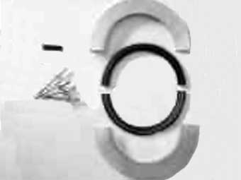
� D&D seal adapter kit�
� A D&D Fabrications adapter kit is required to install a special rear main seal between the Rover block and the Buick 300 crankshaft. Installation is very simple and requires no machining other than drilling five small holes, one in the main bearing cap and four in the back of the block. Detailed instructions come with the kit.�
�
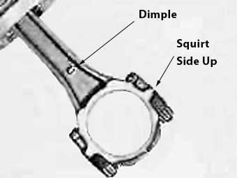
� Correct rod orientation�
� There are two requirements for proper connecting rod installation, whether you use the 215 or the Rover rods: �
� (1) On one side of the rod beam is a cast-in dimple, as shown at right. The rods must be installed with this dimple toward the front of the engine on the right bank cylinders and toward the rear on the left bank. The dimples on the rods on each crank journal will be facing one another.�
� (2) Each of the rod caps have oil spurt holes on one side, next to the bolt. Assembly must be made with the spurt hole "up" as shown above.�
� Use pre-1996 Rover headbolts or those for a Buick/Olds 215. An alternative is a set of ARP p/n 124-4003 studs. The '96 and later Rover head bolts are torque-to-yield, so should not be reused, and are costly. Buick 300 head bolts are 1/4" shorter than the early Rover or 215 fasteners, as they were designed to thread into a cast iron block.�
� Disclaimer: This page was researched and written by Kurt Schley. Views expressed � are those of the author, and are provided without warrantee or guarantee. Apply at your own risk.�