
�
 �
�
An Overview of Suspension Design Parameters
� as published in British V8 Magazine, Volume XVI Issue 1, May 2008�� by: Larry Shimp�
�
Introduction
�� For best handling, the tires should remain perfectly flat on the road surface at � all times. On a go-kart, this is accomplished by having all axles rigidly � attached to the chassis. Impressive cornering performance can be obtained by � a go-kart on flat pavement! However, a suspension system is needed to allow a � car to be used on real roads. This creates compromises that keep the tires from � always remaining flat on the road, and also leads to undesirable weight transfers � that exaggerate the loading on the outside tires in a corner. This article provides � an explanation of fundamental suspension principles and recommendations for � achieving optimum suspension performance.�
� �General Considerations
�� A solid axle tends to keep the tires flat on the road because the axle doesn't � lean with the body. However, with all but very low profile tires, the outer � tire will compress during cornering, and allow some tilting of the axle. For � independent suspensions, geometrical considerations are much more complex. This � is because the suspension is attached to the body, and as the body leans there � is some type of geometrical mechanism to keep the wheels (especially the outer � wheel in a turn) from leaning as much as the body. There are also interactions � between the front and rear suspensions in terms of roll center and roll stiffness. � The roll center of a suspension design is the theoretical point that the body � pivots around as it leans. This can be drastically different between front and rear � suspensions. Roll stiffness is the resistance to body roll, and it usually one � of the easiest suspension design parameters to modify. Roll stiffness plays a � large role in steering responsiveness and in "understeer" or "oversteer" � characteristics.�
�� Another function of the suspension is, of course, to allow steering. This � is mainly a function of the front suspension, but the rear suspension can � also create a steering response of its own. In addition, the rear suspension � has an effect on the driveline performance in terms of torque transmission.�
� �Weight Transfer, Steering Neutrality, & Understeer vs. Oversteer
� �Springs and Unsprung Weight
��
Springs serve a purpose in keeping the wheels in contact with the road on �
less than glass-smooth surfaces. As the tires roll over bumps, they tend �
to bounce. Springs and shocks control this and help to keep the tires on �
the road most of the time. However, the shocks damp the spring action by �
reacting against the relatively stable car body. Without very stiff springs, �
the entire car tends to bounce, and there is no stable platform for the �
damping action to react against. The result is less time for the tires to �
be on the ground. �
�
High unsprung weight in relation to the body weight aggravate this problem. �
Unsprung weight is the weight of the parts not supported by the springs. This �
generally includes half the weight of the spring itself, which is significant �
only for metal leaf springs, and not for coil springs. When the unsprung weight �
is high in relation to the car body, the suspension movements tend to move the �
body more, and there is no longer a stable mass for the dampers to react against. �
Unsprung weight is not too much of a problem with an independent front suspension. �
It can be decreased by going to aluminum brake calipers, and is increased by �
wider wheels and tires. The ultimate solution is a new, light weight �
aftermarket suspension system. In the rear, the live axle weight is significant, �
but so are the metal leaf springs which weigh close to 40 pounds for the pair. �
An independent suspension will reduce unsprung weight the most, but a switch �
to one of the coil spring conversions will help with a live axle. Also, keep �
in mind that some American live axles (such as the Ford/Currie 8") actually �
weigh significantly less than the MGB axle.�
 �
�
Sway Bars
��
Body lean should be controlled mainly by anti-roll bars ("sway bars"). An �
alternative is to install really stiff springs, but, as explained above, �
this is not a good solution. Ideally, the springs should be relatively soft, �
with good damping, so the tires remain in contact with the road, and stiff sway �
bars should be used to control body lean. �
�
In theory, a stiff front bar increases understeer because it transfers more load �
to the outside front tire. In reality, a stiff front bar can often reduce �
understeer because it also improves the geometry of the tire contact as it �
decreases lean. �
�
A rear sway bar, with a live axle, is more predictable in its effects. The rigid �
axle means that tire geometry is always relatively good, so a sway bar will �
increase oversteer (reduce understeer) by decreasing the overall grip in the �
rear as it transfers load from the inner tire to the outer tire. A consequence �
of this load transfer is that there is more of a need for a limited slip �
differential. Therefore, one may wonder why a rear bar is needed at all. The �
advantage is that body lean cannot be completely controlled only by a front bar, �
and reduced lean (with a rear bar) can improve the geometry and thus grip of �
the front end. Best results are obtained when the front and rear grip are equal. �
Having high grip at the rear does not help cornering speeds if the front loses �
grip long before. Another advantage is that reduced lean makes the car much �
more responsive to steering inputs. Finally, with overall reduced body lean, �
weight transfer to the outer tires will be decreased somewhat, partially �
cancelling out the detrimental effects on the rear.�
�
With many of the more exotic MGB rear suspension systems it is impossible to �
install the stock MGB rear sway bar. However, with a chrome bumper car, at �
least, it is relatively easy to fit a sway bar to the bottom of the battery �
boxes. A front bar from a narrow car such as a Midget or Austin Healey 3000 �
can work, as well as a cut down MGB front bar. �
Shock Absorbers ("Dampers")
��
Many British cars come with lever dampers, rather than the more modern tube dampers. �
Other, even older forms of dampers are friction dampers, and inertia dampers. Friction �
dampers are like a sort of lever damper, but they have friction disks at their pivot �
point. They are easy to adjust by tightening or loosening the joint screw and they do �
work, but not very well. It is generally desirable to have more damping on the rebound �
rather than on the initial compression stroke. This keeps the suspension compliant �
with road irregularities, but stops oscillation on the rebound. Friction dampers have �
the same damping force in both directions. And, of course, they are subject to �
mechanical wear so do not hold their settings very well. �
�
Inertia dampers consist of a weight attached by a spring to a suspension arm. As the �
suspension moves, the weight opposes the movement through the spring. This system was �
used mainly on older French cars (as a supplement to friction dampers), and was �
effective with the soft suspensions these cars had. Careful engineering of the weight �
and spring was needed so that harmonic vibrations were not set up. �
�
Hydraulic dampers work by pumping fluid through small passageways, and spring loaded �
one-way valves for extra resistance. The two basic configurations are lever and tube.�
�
Lever dampers are hydraulic and work the same basic way as typical tube dampers. The �
main objection is that they can overheat and fade. Fluid capacity is limited, and, even �
more importantly, the cooling surface area is limited. As the fluid heats up, its �
viscosity decreases, and so the damping resistance goes down. For mild street use, �
lever dampers are fine, but for higher performance, fade can become an issue.�
�
Tube dampers are universal. They are simple, have good cooling, and can be purchased �
in all kinds of configurations, including models with adjustments for damping force. �
 �
�
Tire Selection
��
Tires are the medium by which the car interacts with the road. The suspension is �
designed to provide the best functional conditions for the tires, but the ultimate �
results are limited by the characteristics of the tires.�
�
The two basic types of tire construction are bias-ply and radial. Bias-ply tires have �
cris-crossed layers of reinforcing cord (usually 4 layers). Radial tires are so named �
because they have radially wrapped cords that run across the tread and though the �
sidewall to the bead (usually 2 layers), and also a circumferential layer of cords �
(usually 2 layers of steel wire) under the tread (only). Bias-ply tires have nearly �
constant stiffness over their whole exterior; the tread's stiffness isn't much different �
from the sidewalls. Therefore, the tread doesn't have any special tendency to stay flat �
on the road, and it doesn't track especially well. Radial tires have much more stiffness �
in the tread area than in the sidewalls, which tends to keep the tread flatter on the �
road and thus increases tracking stability. At this time, use of bias-ply tires is mainly �
limited to motorcycles (for obvious reasons) and to vintage show cars. They're also �
sometimes used for drag racing slicks where the tire sidewalls have huge amounts of �
torque to transmit. �
�
But almost all cars benefit from installation of radial tires. Sometimes it's said that �
older cars, including classic British sports cars, were designed for bias-ply tires, and �
will not respond well to radial tires. Not so! Designers in that era lacked the resources �
to do this. As radial tires began to come into general use in the 1960's, it would have �
been counter-productive anyway because radial tires were better in all ways. There may be �
certain suspension settings that are different with radial tires (they favor more caster �
angle and less toe-in) but the differences are minor. Be aware, however, that many old �
wheel rims that were designed for tube-type bias-ply tires don't grip a radial tire bead �
properly and can be dangerous with radial tires. Of course, most V8 cars will have major �
suspension modifications anyway, which is what this article is about, so the original �
design parameters of the car are irrelevant. �
�
Aside from the type of construction, other major parameters are tread compound and �
tread design. Summer tires are constructed with soft rubber that works very well on �
hot road surfaces. On colder road surfaces, summer tires give significantly reduced �
traction. Winter tires have a high silica tread compound which is soft at cold temperatures, �
and that gets even softer at summer temperatures. These excessively soft tires never �
have very good grip on dry roads, and will wear very quickly if used for performance �
driving. All season tires are made from rubber which is somewhat harder than either �
summer or winter tires, and they also contain silica. The silica acts like sandpaper �
and increases traction on cold surfaces and on ice, but it reduces grip on hot, dry �
pavement compared to the pure rubber of summer tires. These tires do not give either �
optimum summer or winter performance, but can be a reasonable compromise. If the car �
will not be driven in the winter, it makes sense to get summer tires. Racing tires �
are like summer tires, but even better. However, they wear very rapidly, and some are �
not even street legal. Racing tires also tend to be noisy and harsh, which makes them �
less well suited for use with "real" road conditions, but they can make a dramatic �
improvement in track day use or in autocross times.�
�
Tread design affects ride, handling, noise, and traction on wet roads. Street tires are �
designed with relatively deep tread patterns and also typically with wide grooves to �
shed water. However, the deep tread reduces tire response because the tread blocks tend�
to squirm independently of the tire body. Dry course racing tires have much shallower �
treads, or no tread at all (e.g. racing "slicks"). This gives the maximum rubber contact �
and tire stability, but they are very dangerous in the rain because water builds up under �
the tire causing the car to hydroplane. Most of the noise generated by tires is from �
the tread design. It arises as air is compressed and released from the tread grooves, �
and also from vibrations in the tire itself. If you want a quiet tire, the best bet �
is to look at the ratings on Tire Rack (or a similar website). There is no reliable way �
to predict noise from just looking at a tire, though one favorable design feature is a �
continuous center rib. �
�
Tire width should be as wide as possible, assuming a reasonably functional suspension �
geometry. The classical friction equation is that frictional force equals a coefficient �
of friction times the force per unit area. Force is the weight on the tire, and area �
is the tire contact patch. In general, as the tire gets wider, the contact patch gets �
bigger, and the force per unit area (pounds/square inch) goes down. But the increased �
area means the frictional force remains about the same. However, this simple equation �
does not apply to tires! A wider tire and a large contact patch always generates more �
frictional force, and maximum performance is always achieved with as wide a tire as �
possible (assuming that the suspension geometry can keep the tire in reasonable contact �
with the road).�
�
Remember that the goal is to have as much tread surface as possible on the road. This �
is a function of the suspension as well as the tires. The more vertical the tires are, �
the flatter the tread will be on the road. Compared to skinnier tires, wider tires lose �
effectiveness more rapidly as the tires are tilted from vertical because the loading �
across the wider tread varies more as tilt increases. Radial tires are one solution, �
because the relatively stiff tread and relatively flexible sidewalls help to isolate �
the tread from the tire tilt.�
�
The ultimate solution however is to reduce body lean as much as possible, and �
optimize the suspension geometry to minimize the effects of what body lean is left.�
�
Tire air pressure is another issue that shouldn't be overlooked. Under-inflation results �
in unstable tire response. The only benefit of low air pressures is a slightly softer ride, �
but the disadvantages are huge. One of the main reasons MG's "MGC" model acquired a poor �
reputation for handling (and specifically for excessive under steer) is that the press �
preview cars had tires inflated to only 20 psi in an attempt to impress the journalists �
with a soft ride. I have found that about 35 psi works well with my tires, and higher �
pressures can sometimes be beneficial. (Don't exceed the tire manufacturer's maximum �
recommended inflation pressure!) �
Tire/Body Interference
� �
This condition, which is most likely to occur at the rear, should be avoided for �
several reasons, including the possibility of a catastrophic accident. One consequence �
that comes to mind is that heavy tire/body contact can wear the tire side wall and �
lead to a blowout, but that is one of the least likely effects. Much more common is �
light contact between the tire sidewall and the inside of the outer fender, especially �
as the suspension is compressed. While tire wear will be minimal, it can lead unstable �
cornering response as the tire friction raises (or lowers) the body until the forces �
overcome the tire friction, leading to sudden settling, followed by a new round of �
tire induced motion. In extreme cases this can lead to loss of control. �
�
But by far the most serious problem is if the tire tread ever contacts the inside �
top of the wheel well. The resulting friction will tend to drive the wheel backwards �
with great force and great consequences. The prototype MGB with swing axle rear �
suspension encountered this on a test drive, and the result was that as the wheel �
was forced backwards, its longitudinal arm broke, the tire went under the car, �
and the car overturned. Luckily the driver escaped without serious injury. Therefore, �
check carefully when fitting significantly larger tires or a much lowered suspension. �
Make sure the bump stops will be adequate to prevent tread contact.�
�
An easy way to check for tire contact is to jack up one corner of the car, which �
will usually fully compress the diagonally opposite suspension unit. Even if �
clearance appears to be adequate by this test, keep in mind that this is only a �
static test, and the suspension can move under load. In terms of side clearance, �
for a stock leaf spring axle, maybe about 1/4 inch of extra side clearance is �
needed. With a Panhard rod with nylon bushings or heim joints, maybe only 1/16 �
inch of clearance is needed. In terms of tire clearance at the top of the wheel �
well, bump stops can compress a fair amount under impact loads, so probably 3/4 �
to 1 inch of clearance is needed.�
 �
�
Body (Chassis) Rigidity
� �
A rigid chassis structure is highly desirable. Even if the suspension geometry is �
optimized, body flex can upset the geometry and lead to less than optimum "real �
world" results. Generally, flex shows up as sloppiness and poor transitional �
response such as when entering a corner - a "vagueness" in the driver-feedback �
loop. This flexing makes a car less predicatably responsive to suspension tuning: �
it becomes more difficult to evaluate the efficacy of changes to the sway bars �
or to tire pressure. �
�
It's interesting to compare the Porsche Boxster and Cayman models. Both cars �
share the same basic platform and suspension, but the Cayman definitely handles �
better. The closed Cayman body has about 50 percent more torsional rigidity than �
the open Boxster so the Porsche engineers decided that the Cayman body could take �
both increased spring rates and stiffer sway bars compared to the Boxster. �
�
Generally speaking, unit body cars (such as MGB) tend to be more rigid than cars �
of comparable weight with body-on-frame construction (such as TR6); closed cars �
(GT's) tend to be more rigid than convertibles. Although the MGB featured a �
notably stiff chassis for its era, it comes nowhere close to the strength of �
many modern cars. Furthermore corrosion, fatigue, and/or inadequately repaired �
collision damage can substantally (and sometimes unpredictably) reduce the �
rigidity of any automotive chassis over its service life. �
�
Restraint is called for when performing suspension upgrades. If you notice door �
gaps changing during cornering or "scuttle shake" on bumpy pavement, a point of �
diminishing returns has been reached. It's time to soften up the suspension or �
add chassis reinforcements.�
Some chassis reinforcements appear so modest, one might incorrectly discount their �
efficacy. The MG Rover "RV8" model demonstrated to us that there were significant �
gains to be had just by �
strengthening the forward leaf spring mounts of the MGB bodyshell. "Seam welds" �
are a well proven technique for strengthening the chassis by adding new welds �
redundant to original-equipment spot welds. �
�
Then there are more elaborate solutions. Racing-style roll cages can be much more �
than just safety equipment! Tied strategically into the body of a race car, �
roll cages in many cases double chassis rigidity. Even less elaborate roll cage �
installations can add enough �
rigidity to dramatically improve the handling characteristics of a street-driven �
sports car, especially if the suspension is tuned �
to leverage the added potential. There can be tradeoffs though, such as increased�
noise and vibration in the driver environment or inconvenient egress. �
Rear Suspension Design Considerations
�Live Axle Rear Suspensions
��
The simplest rear suspension for road cars consists of a solid rear axle suspended �
on leaf springs. The springs provide all the axle location functions and also �
provide springing to accommodate bumps. For high performance applications, this �
leaves much to be desired. On traditional rear-wheel-drive sports cars, the rear �
axle location is affected by both braking and accelerating forces. �
�
As most MGB V8 owners have discovered, with the torque of a V8, the rear springs �
wind up during acceleration which can lead to "tramp". The ring gear is connected �
to the ground through the wheels and tires. As the pinion puts force on the ring �
gear, the pinion tends to climb up the ring gear, which turns the whole axle �
housing. This twists the springs to the point where the spring torque exceeds �
the driving torque, at which point the axle snaps back, causing a judder. There �
are many potential ways to attack this, including: (a) reinforcing the front of �
the spring, (b) adding a parallel radius bar below the spring, and (c) adding a �
"pinion snubber" (which is a rubber stop above the pinion housing that restricts �
upward movement). �
�
The driving force of the axle is transmitted through the two front spring mounts. �
On MGB's (especially later-model rubber bumper MGB's, which have a different �
attachment bracket and ride height) this can induce chassis flex. One way to �
cure this is to weld in reinforcing bars between the spring mounts and the center �
cross member.�
�
Enjoying this article? Our magazine is funded through the generous support of readers like you!
�
To contribute to our operating budget, please click here and follow the instructions.
�
(Suggested contribution is twenty bucks per year. Feel free to give more!)�
Side-to-Side Axle Location
��
On hard cornering, leaf springs allow some side-to-side movement of the axle. This �
reduces steering response and precision, and can lead to the tires rubbing on the �
inner fender lips. To a limited extent, side-to-side axle movement can be addressed �
by selecting stiffer spring bushings and/or more robust spring shackles. For more �
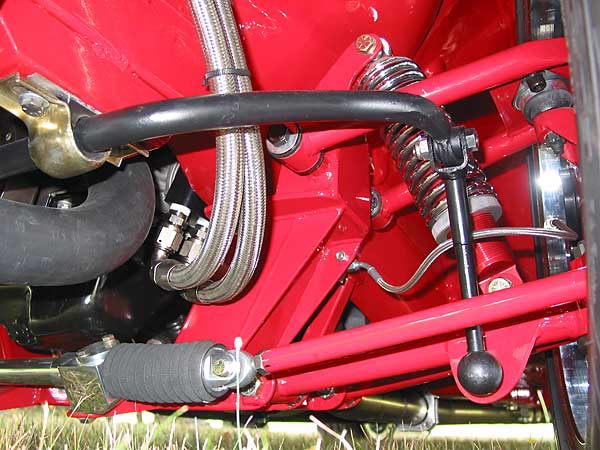
positive control, a popular fix is to install a Panhard rod (a.k.a. "Panhard bar"). �
A Panhard rod is a kind of torque rod that's installed horizontally, parallel to �
the axle, with one end secured to the axle and the other end secured to the body. �
�
A Panhard rod can be a simple and economical solution, but it's not a perfect one. �
To be effective, the Panhard rod and its mountings must be sufficiently rigid. The �
Panhard rod should be installed level, and usually it should be mounted as low as �
feasible. The rod itself should be as long as feasible. �
�
�
 �
�
Digression: Why Are Longer Suspension Links Often Better than Short Ones
��
Suspension links are often used to restrict movement in one axis. A Panhard rod is a �
great example: its purpose is to restrict side-to-side motion of the car's axle �
relative to its body when the car is turning. However, when the car goes over a bump �
the Panhard rod pivots out-of-parallel with the axis and body. As one end of the bar �
travels in an arc, it forces unwanted side-to-side movement. �
�
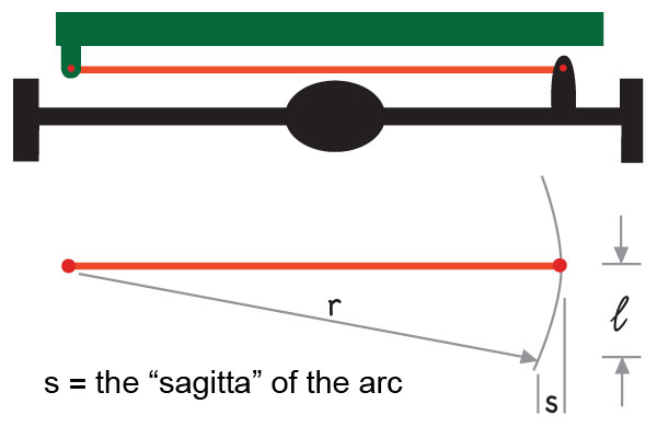
How much? The answer can be found by applying a simple mathematical formula: �
�
s = r - (r2 - l2)0.5�
�
In geometric terms, "s" is called the "sagitta" of the arc. As you can see in the�
illustration, the sagitta's length is equal to the forced side-to-side motion that's �
induced on a bump. Of course the dimension "r" equals the radius of an arc, and in �
the illustration r is equal to the length of the Panhard rod. The amount of vertical �
movement = "l". (Technically, "l" equals one half of the length of a "chord".) �
�
When subjected to a three-inch tall bump in the road, a 12" long Panhard rod would �
subject the car to a horizontal body movement of 0.381", which is enough that most �
drivers would perceive it as a noticeable "shimmy" or, in other words, as a "bump �
steer" effect initiated from the rear of the car. By comparison, a 36" long Panhard �
rod in the same situation would subject the car to a horizontal body movement of 0.125". �
That's unperceptible to most drivers. �
�
There's plenty of room to package a 36" Panhard rod on any typical British sports car. �
In terms of geometry, longer is simply better. Incidentally, Panhard rods aren't the �
only place this rule of thumb applies. It's also true for other types of suspension links.�
�
� �
�
Typically, a well designed Panhard rod provides a big improvement over just leaf �
springs. Another step up is a Watts linkage, which is like a Panhard bar, but with �
a center linkage that keeps the axle centered in the chassis at all times. As far �
as I know, there is no readily available Watts linkage kit for British cars, but �
custom installations have been made. Note: Panhard rod or Watts linkage installations �
only help cornering, and not torque transmission. �
�
It should also be noted that a Panhard rod can significantly alter the roll center �
height of the rear suspension. On a leaf sprung live axle without a Panhard rod, �
roll center height is very nearly at axle centerline. (Technically, roll center �
height is found by drawing a line from the front spring eye to the lower shackle �
bushing, and observing where the line crosses the vertical plane of the axle �
centerline.) When you add a horizontal Panhard rod to the leaf spring rear suspension, �
the roll center height is relocated to very nearly the height of the Panhard rod.�
�
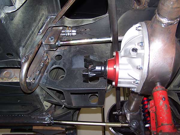
There is also the multi-link rear suspension. It consists of at least two parallel �
trailing arms for front to rear location that are attached to the bottom of the �
axle; and two angled upper arms (or one triangle arm) that provide lateral location �
and also torque control. These systems are always used along with coil springs. �
There is now a kit for MGBs (vendor). In a much more difficult conversion, several �
people have installed new rear frame sections on TR6s to get the 4 link suspension. �
Frame sections are made for street rod fabricators and they can be adapted.�
�
Multi-link suspensions can allow rear axle steering under high cornering forces as �
the suspension bushings deflect. Obviously the more rigid the bushings (up to the �
extreme case of Heim joints) the less deflection. Rear steering reduces �
responsiveness and precision, but the associated softer bushings make the car much �
more civilized in terms of road noise and vibration. �
�
There are independent rear suspension kits available for the MGB and others can be �
adapted such as the Jaguar unit. The geometrical consequences of these are similar �
to double A-arm front suspensions, covered in the next section. Semi trailing arm �
suspensions like that found on TR6s will not be covered, nor will McPherson strut �
suspensions as these generally aren't found on vintage British sports cars.�
Front Suspension Design Considerations
��
�
As was mentioned earlier, independent suspensions tilt with the body, and so need �
"camber gain" as they are compressed to keep the wheels upright in a corner. The �
basic mechanism for this is by using long lower arms and short upper arms. The �
lower arms trace a longer arc when they move than the upper arms. This results in �
less lateral deflection at the bottom of the suspension than at the top, leading �
to an increase in negative camber on the outside wheel in a turn. For best results, �
the lower arms should be set at a static ride height so they point down towards the �
wheel, or are, at worst, level; while the upper arms should point up towards the �
wheel. Upon deflection, the lower arms will move the bottom of the wheel out as �
they go from pointing down to level, then start to move the wheel in as they move �
up from level. The upper arms will always pull the upper part of the suspension �
inward as they pivot upward, and the movement will be to a greater extent than the �
lower arms, thus providing camber gain. �
�
The front roll center is located on a point on or above lines extrapolated inward �
along the lower control arms. This means that as long as the arms are level, the roll �
center is no lower than the inner pivot points of the arms. Once the suspension is �
lowered so the arms point upward towards the front wheels, then the roll center can �
go "underground". While there will still be some camber gain in this situation, this �
low roll center is why the suspension should never be lowered so that the arms slope �
upward. With the rubber bumper cross members used on many MGB V8 conversions, not �
lowering the suspension can result in an undesirably high ride height. The solutions �
to this are: (a) live with it (fine for street driving), (b) stiffer sway bars to �
reduce body roll (see below), (c) custom drop spindles, (d) using a chrome bumper �
suspension by lowering the steering rack, and (e) custom front suspensions (vendor). �
A mismatch between front and rear roll centers (almost always with a lower front �
center) tends to give less predictable handling. It can cause, for example, extreme �
understeer followed by sudden oversteer. Matched roll centers result in a more �
linear and predictable response.�
�
Longer lower A-arms can be used to increase static camber, and so lead to less of �
a need for camber gain in cornering. However, in a turn the inside wheel will have �
an even more unfavorable geometry; and in straight line travel, the tires will not �
be as evenly loaded across the tread, especially with wide tires. This can decrease �
braking efficiency. �
Steering Geometry
�� There are many factors in play: toe in/out, Ackerman effect, scrub radius, and caster angle. �
� �Toe-In (or Toe-Out)
��
"Toe-in" is when the wheels point towards each other and "toe-out" is when the wheels �
point away from each other. The ideal situation for a rear wheel drive street car is �
slight toe-in. As the car moves forward, drag from the tires tends to push the alignment �
toward a toe-out condition. Slight toe-in stabilizes the steering by slightly �
"preloading" the tires inward. If a toe-out condition exists at speed, the steering �
becomes noticeably unstable. Sometimes toe-out is set on a road race car to deliberately �
create instability in order to improve initial steering response, but this characteristic �
isn't pleasant in daily driving.�
�
Logically, toe-in (or toe-out) should probably be measured and communicated as an angle, �
but to accurately calculate the included angle, as measured with typical shop equipment �
(such as improvised trammel bars or strings) would require trigonometry. So, the �
standard convention is to dumb toe-in measurements down to fractions of an inch as �
measured between tires at the three and nine o'clock positions at their circumference. �
(Obviously, toe-in measurements are thus affected by tire diameter.) The desired amount �
of toe-in is also largely a matter of driver preference. Many MGB owners like as little �
as 1/16" of toe-in, and few people recommend more than 3/16" of toe-in. �
� Theoretically, toe-in should be reduced as tires get wider. Wide tires perform � best if they are as parallel as possible since "scrub" due to misalignment is � amplified across a wide tread. With narrow tires, it is ok to err on the side of � excessive toe in, but more precision is beneficial as tires get better.�
� �Ackerman Effect
��
The two front wheels follow different arcs in a turn, with the inner wheel taking �
a tighter turning radius. The compensation for this is known as the "Ackerman" effect. �
It is mainly important in low speed maneuvers at extreme steering lock such as parking, �
and has a minor effect on normal driving. Still, it should be understood.�
�
With a rack and pinion, and with the rack forward of the front axle, Ackerman geometry �
is achieved by having the steering arms make an angle with the tie rods that is slightly �
less than 90 degrees. As the wheels are steered, the outer arm moves less as its angle �
with the tie rod goes through 90 degrees and continues to widen. The inner steering arm �
continues to make a tighter and tighter angle with the tie rod and so moves a greater �
distance, making a tighter turning radius. Normally, this geometry is not adjustable; �
but rubber bumper MGs have the rack moved slightly forward, which makes the tie rod �
to steering arm angle closer to 90 degrees at the straight ahead position, and so is �
less favorable. Moving a chrome bumper rack forward to clear an engine can also lead �
to a reduction in the Ackerman effect.�
�
In cars with the steering rack behind the front axle, the tie rods need to make an �
angle with the steering arms that is greater than 90 degrees in order to achieve the �
proper Ackerman geometry. �
�
 �
�
Bump Steer
�� As the front wheels move up and down, the tie rods move with them. Ideally, the tie � rods should pivot along the same radius as the front suspension. In addition, the � tie rod length and position should be such that the outer end of the tie rod falls � on a line that is projected onto the steering axis, and the inner ends of the tie rods � should fall on the planes defined by the upper and lower inner A-arm pivot points. � If these conditions are not met, then the effective length of the tie rods will vary � with suspension travel, causing a slight turning effect on the wheels; which is called � "bump steer". Because the upper and lower A-arms pivot on different radii, it is � impossible for the tie movement arc to exactly match the front suspension arc so bump � steer will always exist to some extent. However, the tie rod geometry should be as � close to ideal as feasible, with any residual mismatch leading to toe-in upon suspension � compression. If toe-out occurs upon suspension compression, the steering will feel � unstable. (With slight toe-in, the effect is usually unnoticeable. This subject was � also discussed under "toe-in/toe-out"). The standard MG front suspension has very � good bump steer geometry, but lowering the suspension excessively (generally over � an inch) moves the static condition away from the design parameters, and undesirable � bump steer can be introduced. This is, of course, more likely to be a problem with � the later "rubber bumper" suspension. A possible cure is to have the steering arms � repositioned by bending - but this calls for an expert with the proper tools and � experience. Of course, there is still the problem with the roll center...�
� �Scrub Radius
��
This is the distance between the center of the tire tread and the point where the �
kingpin axis intersects the ground. Essentially all rear wheel drive cars are designed �
to incorporate a positive scrub radius, meaning that the tire contact center is outside �
the kingpin pivot point. A large scrub radius gives lighter steering because the tires �
can roll in an arc as the steering wheel is turned. If the scrub radius is zero, then �
the tire has to be twisted on the ground, and the steering effort is highest. However, �
too large of a scrub radius makes the steering very sensitive to road surface �
irregularities. As the tire hits a bump, it will tend to turn the steering wheel to �
the side. Technically, this is not bump steer, although it is associated with bumps �
and steering. Having a zero scrub radius also results in unstable steering as the drag �
from the tires can switch back and forth since there is no "preload" condition. The �
ideal situation is to have a slight positive scrub radius such that the normal drag �
from both front tires is slightly loading the steering, and yet not so much that road �
bumps cause too much of an additional drag. �
�
The way to control scrub radius is by the wheel offset. Wheel offset is a measure of �
the wheel hub mounting surface in relation to the wheel center (width). A positive �
offset means the mounting surface is offset towards the outside of the wheel, and a �
negative offset puts the mounting surface towards the inside of the wheel. As designed, �
an MG has about a 24 mm positive offset. �
�
A smaller positive wheel offset, or a negative offset (as is sometimes used with wheels �
to fill the fender wells on MGB Sebring conversions) can lead to a very excessive scrub �
radius. If a wider front track is desired, then it is better to get longer A-arms rather �
than decrease the wheel offset. Longer A rams are available for several front suspensions �
such as Fast Cars and Hoyle. �
�
Even with a stock width MGB, the standard scrub radius can be excessive. Wide wheels and �
tires load the steering more than the skinny original tires, so bump sensitivity can be �
increased. I found that by going to wheels with a larger, 35 mm offset (and 5/8 inch �
longer A-arms) steering stability was significantly improved.�
Caster Angle
��
Positive caster means the king pin axis tilts rearward (as on a bicycle). Negative caster �
means the axis tilts forward (as on a shopping cart). In an automobile suspension design, �
caster serves two purposes: it increases steering stability and it helps camber gain upon �
cornering. Positive caster is associated with stability. Note that a bicycle tends to �
track straight if left on its own, while the casters on a shopping cart tend to oscillate. �
This effect is also obvious when a car is driven at high speed in reverse. The stability �
(self centering) effect of caster is associated with the car being slightly raised as the �
wheels pivot from the straight ahead position. Caster is another area where there is a �
question of driver preference. In the case of the MGB, the suspension was originally �
designed with about seven degrees of caster, but caster reduction kits are offered to �
reduce caster and thereby reduce steering effort. These kits make more sense for cars �
with radial tires (instead of the bias ply tires) and smaller diameter steering wheels.�
�
Another effect of positive caster is that, on a turn, it makes the top of the outer wheel �
tilt in and the top of the inner wheel tilt out, thus countering body lean and complimenting �
camber gain to some extent. This is a very desirable effect, and all modern cars with power �
steering have generally much greater caster angles than older cars with manual steering.�
Software Programs for Suspension System Analysis
� http://www.auto-ware.com/software/asgp/asgp.htm�� http://www.performancetrends.com/rc.htm�
� http://www.bevenyoung.com.au/suswin.htm�
� http://www.myzips.com/software/SusProg3D--SUSPENSION-BY-DESIGN.phtml � �
� Disclaimer: This page was researched and written by Larry Shimp. Views expressed � are those of the author, and are provided without warrantee or guarantee. Apply at your � own risk. The design and condition of the suspension has a significant influence on � safety. Only people with appropriate qualifications should ever carry out suspension � work. It is strongly advised to consult a professional before starting any suspension � project, and at the very least, to have a professional mechanic inspect any work that � has been carried out.�
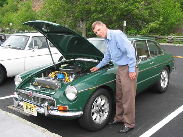
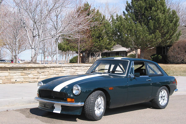
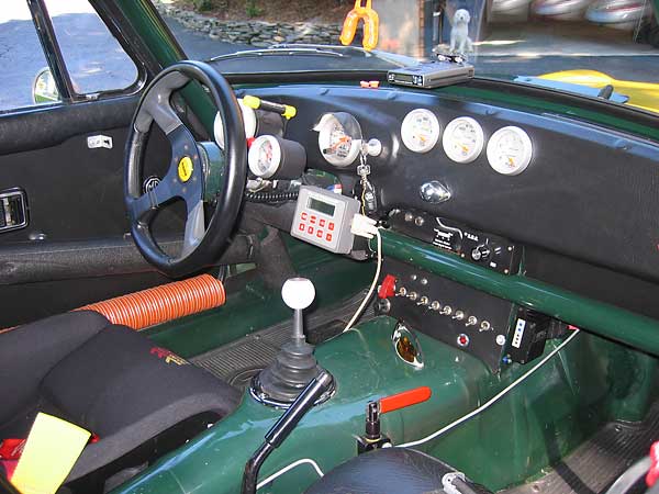
� Photos by Curtis Jacobson, Dan Masters, and Lorenz Hassenstein respectively, for British V8 Magazine.
� Sagitta illustration by Lisa Kerans for British V8 Magazine. All rights reserved.�