
�
�
� �
� by: Jim Blackwood�
� Many of us have lusted sincerely since adolescence for a car with a "blower". � For me it was a TV commercial where a teenaged boy taunts his dad by playing � with the throttle linkage on the bug catcher while the old man is trying to � talk. That car was just too cool. In any case for some reason that big belt � drive sticking through the hood just struck some primitive nerve.�
� Having gone the route of the V8 conversion on the MGB, what could be better � than supercharging it? For the BOP 215/Rover V8 this is no small order however � and as a result this car was first fitted with a factory Olds turbocharger. � This was a neat piece of work and gave pretty good performance, but the entire � setup was limited in a number of ways and when the shaft bearing began to � wobble an excuse was born.�
� So this is the story of an MGB fitted with a roots type positive displacement � blower, along with a modern engine management system including fuel injection � and a distributorless ignition. Might as well go the whole route at once I � reasoned.�
�
�
�
�
Supercharging the MGB-V8
� This article appeared in The British V8 Newsletter - Volume X, Issue 2 - May 2002�� by: Jim Blackwood�
� Many of us have lusted sincerely since adolescence for a car with a "blower". � For me it was a TV commercial where a teenaged boy taunts his dad by playing � with the throttle linkage on the bug catcher while the old man is trying to � talk. That car was just too cool. In any case for some reason that big belt � drive sticking through the hood just struck some primitive nerve.�
� Having gone the route of the V8 conversion on the MGB, what could be better � than supercharging it? For the BOP 215/Rover V8 this is no small order however � and as a result this car was first fitted with a factory Olds turbocharger. � This was a neat piece of work and gave pretty good performance, but the entire � setup was limited in a number of ways and when the shaft bearing began to � wobble an excuse was born.�
� So this is the story of an MGB fitted with a roots type positive displacement � blower, along with a modern engine management system including fuel injection � and a distributorless ignition. Might as well go the whole route at once I � reasoned.�
�
�
Or maybe reason had nothing whatsoever to do with it. In any case it was �
accepted at the beginning of the project that the drive and blower would �
stick through the hood. Maybe at some primal level that was the objective. �
At a later stage it was seen that it could be possible to do the conversion �
and have the hood close on it. Therein lies the potential for a serious sleeper �
and this thought will be picked up again later, so if you want to keep the �
stock appearance stay tuned. A little about the patient and the direction of �
the project is in order. The donor car was a 1971 MGB roadster with a very �
checkered past, and not one that would have been selected for restoration �
by anyone but a masochist. So despite anyone's preferences in regards to �
originality of bodywork, interior, or any other aspect of the car this should �
not offend the purists in our midst. They all would have likely consigned �
the entire car to the parts bin or the scrap yard long ago, and it is only �
by virtue of the radical modifications it has undergone that it has survived.�
� In short, the car has been lowered a couple inches, has been widened by some � six inches, sports about twice the stock tread area, extremely oversized front � brakes, and any number of other custom modifications we can touch on later. � The engine in question is a genuine original Olds Turbo 215 which was rebuilt � at Joe Lemley's Racing Engines in Southpoint, Ohio before I got it. Some of � the old drag racers among us may remember Joe as the NHRA class record holder � during the late sixties in the six cylinder class, a distinction he held with � his grey Corvette for two or three years. Anyway, the turbo engines had � unique high compression heads, which in combination with stock Olds 0.030 � over low compression pistons, composition head gaskets, and 0.040" milled � from the heads gives between 8 and 8.5:1 compression. Olds heads were used � rather than Buick because of the even six bolt per cylinder head bolt pattern � which gives better clamping force than either the Buick 5 bolt heads or the � 300 cu in 4 bolt heads and should do a better job of sealing with forced � induction. As boost is expected to be between 5 and 7psi, O-ringing the � cylinders is not needed and the factory valve springs were retained since � high rpm operation should not be necessary. The factory cam was retained as � well for good drivability, and no other significant changes were made to � the heads aside from light port matching and cleanup. �
� Stainless steel was used for all external fasteners, in most cases button � head capscrews, which give a larger head bearing surface than socket head � capscrews, as well as simply looking better. The choice of stainless was a � practical one, to prevent corrosion.�
��
 �
�
�
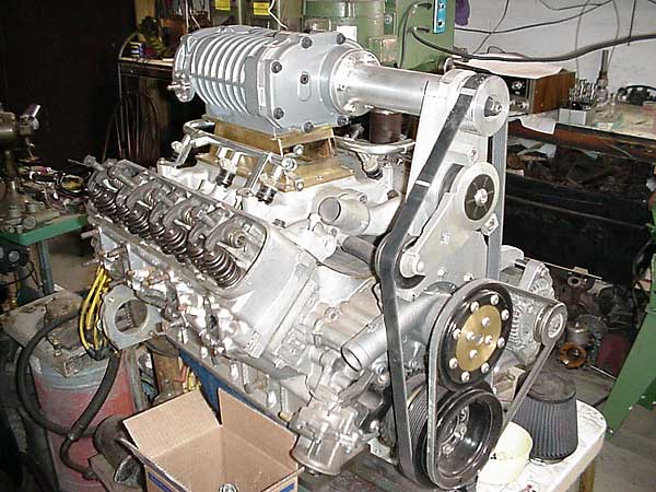
� After a good deal of investigation an Eaton blower was chosen. It is somewhat � oversized for the 3.5 liter displacement, being designed with a 3.0 to 5.7 � liter engine in mind, but that makes it an ideal size for a 4.6 Rover or a � stroker motor. It is overdriven at a ratio of 2.3:1, giving a rotor speed of � about 12,000 rpm at 5,000 rpm crank speed and if overboost becomes a problem � the ratio can be easily reduced with a top pulley change.�
��
�
� The model designation is M-90. It is the 4th generation unit which has an � integral bypass valve, a rear inlet, is specifically designed to work with � multiport fuel injection, and can be mounted in any orientation. As British � car enthusiasts should know, Eaton blowers have been around for a very long � time, and this was an element of the decision. The cost was reasonable at � around $1100 from Magnuson Products in Ventura, CA (magnusonproducts.com) � but at the time of purchase these units were still scarce and I had to � twist Jerry's arm a little to get his guys to ship me one. This blower was � mounted in the conventional location to a brass plenum bolted to a modified � Offenhauser intake manifold. A front support plate was machined from 3/4" � aluminum and mounted to the front of the engine using the water pump bolts. � This plate incorporates the tensioning arm and pulley for the dedicated 7 � rib serpentine belt.�
� The tensioning arm is the Ford 4.6 unit with the rotation reversed and new � stops bolted to the support plate. It is mounted with 1/2" button head � capscrews on a boss countersunk into the plate. The alternator also hangs � from the support plate, having a long 3/8" bolt attaching to the front of � the left head as well. For the lower drive pulley, the hub of the Olds � damper was used and modified as follows. The Ford crank timing wheel was � fitted to the back side and welded into place. Then the center of the Ford � damper was machined to press fit to a machined hub and was tack-welded so � that it couldn't move and the assembly was balanced. This was mounted to � the damper hub using longer pulley and center bolts. �
��
 �
�
 �
�
�
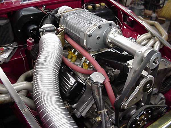
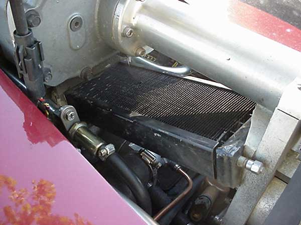
� The outer ring of the Ford damper doubles as the serpentine drive pulley, � and the water pump drive pulley is attached in the conventional way. This � moves the outer pulley forwards a good distance and was accommodated by � using a flat pulley on the Buick 300 cast iron water pump, which is shorter � and has the neck angled rearwards away from the serpentine belt. Since the � nose or drive of the blower was a custom length which is available in 1" � increments the housing for it is made in two pieces. The front cover is � cast and is the same as the standard front cover except for having a � machined boss for attaching the flange of the extension housing. This � extension can be made in various lengths, in my case 8-1/4". That plus � the front cover gives a drive housing length of 10" to the back of the � pulley. The plenum houses a special experimental intercooler using heat � pipe technology, has a sneeze valve on the rear under the blower intake, � and raises the blower above the injector fuel rail.�
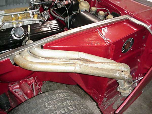
� The Offy manifold was chosen because of the single plane runner design � and large plenum area after removal of the internal flow dividers which � simplified injector placement and made room for the intercooler. The late � Rover fuel rail was used with Ford injectors mounted in aluminum bosses. � These bosses were heli-arced into recesses cut into the runner top � surfaces using a special jig and purpose designed milling cutters, to � closely approximate the placement and angle of the Rover injectors. � Once the jig is bolted to the intake a1/2" drill is all that's needed � to drill the holes and cut the seats for the injector bosses and of course, � it will bolt up to any BOP/Rover intake. It would have been possible to � use an epoxy based adhesive instead of TIG welding the bosses in, but as � I was already having a 3/4" flange welded to the top of the manifold it � wasn't much extra to weld them. On the exhaust side of the heads, flow � is handled by custom fender well headers having 1-3/8" diameter equal � length primary tubes running 35.25" into spiral scavenging 2-3/8" � collectors, from where they dump into header mufflers and exit in front � of the rear wheels. The exhaust system runs through the bodywork and is � accessible by raising the forward tilt hood assembly, and by removing � the stainless grillwork from the flared rocker panels.�
� On the intake side of the blower, fresh air is drawn through a conical � K&N filter behind the radiator grille. Wire reinforced silicon hose � routes this back to the mass airflow meter near the rear of the blower � after which a larger "U" shaped hose connects to the throttle body. A � brass coupler matches the throttle body to the blower inlet. An idle � speed control valve is plumbed in parallel with the throttle body and � no EGR is used. A Ford powertrain control system was used as the � electronics package, featuring the EEC-IV PCM and modular distributorless � ignition cannibalized from a 1993 Crown Vic police cruiser with the � 4.6 liter V8 engine. This system was chosen for its ready availability, � high level of sophistication and its proven high performance potential. � The system has the ability to modify and store engine tuning parameters � based on sensor feedback, and some very good hardware and software � packages are available for under $400 which allow virtually unlimited � programming changes to be made for custom tuning. In unmodified form � the injection system can support power levels over 300 hp. I would � recommend using a system taken from a Mustang though as most of the � tuning work has been done using those computers. There is a large � library of binaries, and GUI software has been well tested, whereas � with the Crown Vic I am breaking new ground.�
��
 �
�
�
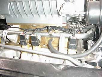
� The stock distributor was cut down and capped with a 1" copper tubing � cap, O-ring sealed to the housing and reinstalled to provide the drive � for the oil pump. This was then reengineered to accommodate a sensor for � cylinder identification. �
� The system will operate without this sensor, but it does provide a useful � synchronization function. Much of the Ford wiring harness was reused, � including fuse and relay blocks. A power distribution block was added, � as well as some 18 fuses and 16 relays. Crown Vic cars utilized a very � handy 3 relay module which is quite good for such things as radiator fans � and headlights, so I couldn't resist adding a few more relays than the � fuel injection system required. The PCM (computer) is mounted in the � passenger's footwell using the Ford bulkhead connector.�
� To do this a small notch roughly an inch square was cut at the front of � the outside edge of the existing RHD brake pedal hole for the PCM � connector, and a cover plate fashioned to hold the box securely using � the recesses molded into the connector body. The result gives a cleaner � appearance than the original cover. The fusebox, one relay box, and � ignition module are on the unused pedal assembly shelf along with the � vapor recovery canister. The other relay box is beside the radiator and � in front of the right side coil. The left side coil is just forward of � the brake pedal assembly, near the engine compartment ventilation fans � which draw air from the engine compartment into the fenderwell area on � both sides. A Ford all-electric cruise control unit is mounted on the � left frame rail at the front of the engine and the control cable is � routed under the intake manifold and up to the throttle-body.�
�
�
�
� In short, the car has been lowered a couple inches, has been widened by some � six inches, sports about twice the stock tread area, extremely oversized front � brakes, and any number of other custom modifications we can touch on later. � The engine in question is a genuine original Olds Turbo 215 which was rebuilt � at Joe Lemley's Racing Engines in Southpoint, Ohio before I got it. Some of � the old drag racers among us may remember Joe as the NHRA class record holder � during the late sixties in the six cylinder class, a distinction he held with � his grey Corvette for two or three years. Anyway, the turbo engines had � unique high compression heads, which in combination with stock Olds 0.030 � over low compression pistons, composition head gaskets, and 0.040" milled � from the heads gives between 8 and 8.5:1 compression. Olds heads were used � rather than Buick because of the even six bolt per cylinder head bolt pattern � which gives better clamping force than either the Buick 5 bolt heads or the � 300 cu in 4 bolt heads and should do a better job of sealing with forced � induction. As boost is expected to be between 5 and 7psi, O-ringing the � cylinders is not needed and the factory valve springs were retained since � high rpm operation should not be necessary. The factory cam was retained as � well for good drivability, and no other significant changes were made to � the heads aside from light port matching and cleanup. �
� Stainless steel was used for all external fasteners, in most cases button � head capscrews, which give a larger head bearing surface than socket head � capscrews, as well as simply looking better. The choice of stainless was a � practical one, to prevent corrosion.�
�
�
� After a good deal of investigation an Eaton blower was chosen. It is somewhat � oversized for the 3.5 liter displacement, being designed with a 3.0 to 5.7 � liter engine in mind, but that makes it an ideal size for a 4.6 Rover or a � stroker motor. It is overdriven at a ratio of 2.3:1, giving a rotor speed of � about 12,000 rpm at 5,000 rpm crank speed and if overboost becomes a problem � the ratio can be easily reduced with a top pulley change.�
�
| �
Enjoying this article? Our magazine is funded through the generous support of readers like you! � To contribute to our operating budget, please click here and follow the instructions. � (Suggested contribution is twenty bucks per year. Feel free to give more!)� |
� The model designation is M-90. It is the 4th generation unit which has an � integral bypass valve, a rear inlet, is specifically designed to work with � multiport fuel injection, and can be mounted in any orientation. As British � car enthusiasts should know, Eaton blowers have been around for a very long � time, and this was an element of the decision. The cost was reasonable at � around $1100 from Magnuson Products in Ventura, CA (magnusonproducts.com) � but at the time of purchase these units were still scarce and I had to � twist Jerry's arm a little to get his guys to ship me one. This blower was � mounted in the conventional location to a brass plenum bolted to a modified � Offenhauser intake manifold. A front support plate was machined from 3/4" � aluminum and mounted to the front of the engine using the water pump bolts. � This plate incorporates the tensioning arm and pulley for the dedicated 7 � rib serpentine belt.�
� The tensioning arm is the Ford 4.6 unit with the rotation reversed and new � stops bolted to the support plate. It is mounted with 1/2" button head � capscrews on a boss countersunk into the plate. The alternator also hangs � from the support plate, having a long 3/8" bolt attaching to the front of � the left head as well. For the lower drive pulley, the hub of the Olds � damper was used and modified as follows. The Ford crank timing wheel was � fitted to the back side and welded into place. Then the center of the Ford � damper was machined to press fit to a machined hub and was tack-welded so � that it couldn't move and the assembly was balanced. This was mounted to � the damper hub using longer pulley and center bolts. �
�
�
�
� The outer ring of the Ford damper doubles as the serpentine drive pulley, � and the water pump drive pulley is attached in the conventional way. This � moves the outer pulley forwards a good distance and was accommodated by � using a flat pulley on the Buick 300 cast iron water pump, which is shorter � and has the neck angled rearwards away from the serpentine belt. Since the � nose or drive of the blower was a custom length which is available in 1" � increments the housing for it is made in two pieces. The front cover is � cast and is the same as the standard front cover except for having a � machined boss for attaching the flange of the extension housing. This � extension can be made in various lengths, in my case 8-1/4". That plus � the front cover gives a drive housing length of 10" to the back of the � pulley. The plenum houses a special experimental intercooler using heat � pipe technology, has a sneeze valve on the rear under the blower intake, � and raises the blower above the injector fuel rail.�
� The Offy manifold was chosen because of the single plane runner design � and large plenum area after removal of the internal flow dividers which � simplified injector placement and made room for the intercooler. The late � Rover fuel rail was used with Ford injectors mounted in aluminum bosses. � These bosses were heli-arced into recesses cut into the runner top � surfaces using a special jig and purpose designed milling cutters, to � closely approximate the placement and angle of the Rover injectors. � Once the jig is bolted to the intake a1/2" drill is all that's needed � to drill the holes and cut the seats for the injector bosses and of course, � it will bolt up to any BOP/Rover intake. It would have been possible to � use an epoxy based adhesive instead of TIG welding the bosses in, but as � I was already having a 3/4" flange welded to the top of the manifold it � wasn't much extra to weld them. On the exhaust side of the heads, flow � is handled by custom fender well headers having 1-3/8" diameter equal � length primary tubes running 35.25" into spiral scavenging 2-3/8" � collectors, from where they dump into header mufflers and exit in front � of the rear wheels. The exhaust system runs through the bodywork and is � accessible by raising the forward tilt hood assembly, and by removing � the stainless grillwork from the flared rocker panels.�
� On the intake side of the blower, fresh air is drawn through a conical � K&N filter behind the radiator grille. Wire reinforced silicon hose � routes this back to the mass airflow meter near the rear of the blower � after which a larger "U" shaped hose connects to the throttle body. A � brass coupler matches the throttle body to the blower inlet. An idle � speed control valve is plumbed in parallel with the throttle body and � no EGR is used. A Ford powertrain control system was used as the � electronics package, featuring the EEC-IV PCM and modular distributorless � ignition cannibalized from a 1993 Crown Vic police cruiser with the � 4.6 liter V8 engine. This system was chosen for its ready availability, � high level of sophistication and its proven high performance potential. � The system has the ability to modify and store engine tuning parameters � based on sensor feedback, and some very good hardware and software � packages are available for under $400 which allow virtually unlimited � programming changes to be made for custom tuning. In unmodified form � the injection system can support power levels over 300 hp. I would � recommend using a system taken from a Mustang though as most of the � tuning work has been done using those computers. There is a large � library of binaries, and GUI software has been well tested, whereas � with the Crown Vic I am breaking new ground.�
�
�
� The stock distributor was cut down and capped with a 1" copper tubing � cap, O-ring sealed to the housing and reinstalled to provide the drive � for the oil pump. This was then reengineered to accommodate a sensor for � cylinder identification. �
� The system will operate without this sensor, but it does provide a useful � synchronization function. Much of the Ford wiring harness was reused, � including fuse and relay blocks. A power distribution block was added, � as well as some 18 fuses and 16 relays. Crown Vic cars utilized a very � handy 3 relay module which is quite good for such things as radiator fans � and headlights, so I couldn't resist adding a few more relays than the � fuel injection system required. The PCM (computer) is mounted in the � passenger's footwell using the Ford bulkhead connector.�
� To do this a small notch roughly an inch square was cut at the front of � the outside edge of the existing RHD brake pedal hole for the PCM � connector, and a cover plate fashioned to hold the box securely using � the recesses molded into the connector body. The result gives a cleaner � appearance than the original cover. The fusebox, one relay box, and � ignition module are on the unused pedal assembly shelf along with the � vapor recovery canister. The other relay box is beside the radiator and � in front of the right side coil. The left side coil is just forward of � the brake pedal assembly, near the engine compartment ventilation fans � which draw air from the engine compartment into the fenderwell area on � both sides. A Ford all-electric cruise control unit is mounted on the � left frame rail at the front of the engine and the control cable is � routed under the intake manifold and up to the throttle-body.�
�
�
For the fuel supply, a '68 fuel tank was used in the stock location. �
This tank does not have a vent so when the vapor recovery system was �
reinstalled a fitting was silver soldered to the fuel filler neck to �
accommodate it, as well as an additional fitting for fuel return. Fuel �
is drawn from the tank in standard fashion by the stock fuel pump and �
sent to a small tank in the spare battery compartment, where a 3/16" �
return line vents any vapors back to the main tank and has a restriction �
to maintain a small level of fuel circulation. With the ignition turned �
on you hear about 3 clicks at a time from the Lucas pump which would �
seem to be an acceptable amount of flow. Below the tank in the battery �
box is a Ford inline fuel injection pump used on the frame rail of the �
dual tank F150 pickups. This pressurizes the line to the fuel rail. The �
Ford fuel pressure regulator is referenced to manifold pressure and �
returns excess fuel to the small tank. With a capacity of 3 quarts this �
will provide ample fuel for short blasts at WOT, and at lower power �
levels the Lucas should be able to keep up.�
� I think that about covers the mechanical end of things, except that � I retained the heater box and grafted on a bigger fan. I also added a � second brake cylinder and inside adjustable balance bar, in keeping � with the car's dirt track racing history. The rear axle is stock late � MGB with custom 5 lug hubs and the tranny is a close ratio Warner T-50 � which is a combination I've been happy with so far. Since I've got a � couple of spare axles lying around I'm not too worried about breaking � it. I've seen where one person said it was as strong or stronger than � an 8" Ford, so I might as well test it some more.�
� The electrical system is a whole different can of worms (or spaghetti � maybe) that I may open later, so let's get back to that sleeper � configuration. The blower housing measures 5-1/2" by 7-1/2" and on � my car the pulley is above the hood about 6-1/2". There's about 7-1/2" � between the base of the blower and the lifter valley cover. By � turning the blower over and mounting it in close proximity to that � cover the pulley would be brought below the hoodline, leaving some � 4" or so above the blower outlet flange. A custom intake is needed � but that isn't overly complicated since there wouldn't need to be a � water jacket to warm the floor of the plenum chamber. A simple cross � ram IR tube manifold with the runners going up and over the blower � to a plenum between the runners and the blower outlet would do the � trick nicely, and there might even be room for an air/water intercooler. � The injectors could fire nearly vertical into the cylinders and all � that's left is a thermostat housing and coolant runners at the front � of the heads. �
�
�
�
� I think that about covers the mechanical end of things, except that � I retained the heater box and grafted on a bigger fan. I also added a � second brake cylinder and inside adjustable balance bar, in keeping � with the car's dirt track racing history. The rear axle is stock late � MGB with custom 5 lug hubs and the tranny is a close ratio Warner T-50 � which is a combination I've been happy with so far. Since I've got a � couple of spare axles lying around I'm not too worried about breaking � it. I've seen where one person said it was as strong or stronger than � an 8" Ford, so I might as well test it some more.�
� The electrical system is a whole different can of worms (or spaghetti � maybe) that I may open later, so let's get back to that sleeper � configuration. The blower housing measures 5-1/2" by 7-1/2" and on � my car the pulley is above the hood about 6-1/2". There's about 7-1/2" � between the base of the blower and the lifter valley cover. By � turning the blower over and mounting it in close proximity to that � cover the pulley would be brought below the hoodline, leaving some � 4" or so above the blower outlet flange. A custom intake is needed � but that isn't overly complicated since there wouldn't need to be a � water jacket to warm the floor of the plenum chamber. A simple cross � ram IR tube manifold with the runners going up and over the blower � to a plenum between the runners and the blower outlet would do the � trick nicely, and there might even be room for an air/water intercooler. � The injectors could fire nearly vertical into the cylinders and all � that's left is a thermostat housing and coolant runners at the front � of the heads. �
�
�
Since the blower inlet is to the rear plenty of options exist for �
the inlet tract. Having completed the project except for final �
debugging and start-up and with the rest of the bodywork yet to be �
done I won't undertake that configuration unless someone else is �
particularly interested in it though. I've still got plenty to do �
to make the car streetable by warm weather.�
��
 �
�
�
� So that's where it stood as of a month or so ago. Now it runs, and � runs well. Getting from there to here would take another article but � to hit the highlights, the first try at start up was a complete � failure. From that followed a complete recheck of the wiring, with � some fairly minor changes, the ignition timing and injector timing � were rechecked about a half dozen different ways, and at last with � fire to the plugs and injectors and all but 3 minor error codes � eliminated, I noticed that only one injector was clicking. A junkyard � trip netted another (older) set of injectors and more importantly, � another fuel pump, injector rail with regulator, and yes, another � relay box. Cobbling it all together I ended up with a cheap but � sophisticated device for back flushing and testing injectors, and � was in the end able to salvage every one of the original injectors, � which was good because they have a better pattern. So I put those back � in, using new O-rings, and by lunchtime cranked her up. Success! (And � as I always say, nothing succeeds like success.) And what a great � success it was.�
� The engine sounded great. Smooth and powerful, and more responsive � than any of these engines I've seen so far. So smooth in fact that � I just had to try balancing a quarter on it's edge on the cowl. Did � it too! Winging the throttle brought such immediate power that it was � almost scary, and the only disappointment in the entire experience was � that when I brought the revs up and held it for awhile it cut out. � I'll get back to that one and find out why, perhaps something simple, � perhaps not. When I immediately let go of the throttle it dropped to � a smooth idle without missing a beat, so at this point I'm not too � concerned.�
� That should be eminently fixable. So now it's back to the bodywork. � With a little luck and some hard work I just may have it back on the � road in another month or two. At the very least I expect to be at the � V8 meet with it in August! �
� Disclaimer: This page was researched and written by Jim Blackwood. Views expressed � are those of the author, and are provided without warrantee or guarantee. Apply at your � own risk.�
�
�
�
�
� So that's where it stood as of a month or so ago. Now it runs, and � runs well. Getting from there to here would take another article but � to hit the highlights, the first try at start up was a complete � failure. From that followed a complete recheck of the wiring, with � some fairly minor changes, the ignition timing and injector timing � were rechecked about a half dozen different ways, and at last with � fire to the plugs and injectors and all but 3 minor error codes � eliminated, I noticed that only one injector was clicking. A junkyard � trip netted another (older) set of injectors and more importantly, � another fuel pump, injector rail with regulator, and yes, another � relay box. Cobbling it all together I ended up with a cheap but � sophisticated device for back flushing and testing injectors, and � was in the end able to salvage every one of the original injectors, � which was good because they have a better pattern. So I put those back � in, using new O-rings, and by lunchtime cranked her up. Success! (And � as I always say, nothing succeeds like success.) And what a great � success it was.�
� The engine sounded great. Smooth and powerful, and more responsive � than any of these engines I've seen so far. So smooth in fact that � I just had to try balancing a quarter on it's edge on the cowl. Did � it too! Winging the throttle brought such immediate power that it was � almost scary, and the only disappointment in the entire experience was � that when I brought the revs up and held it for awhile it cut out. � I'll get back to that one and find out why, perhaps something simple, � perhaps not. When I immediately let go of the throttle it dropped to � a smooth idle without missing a beat, so at this point I'm not too � concerned.�
� That should be eminently fixable. So now it's back to the bodywork. � With a little luck and some hard work I just may have it back on the � road in another month or two. At the very least I expect to be at the � V8 meet with it in August! �
� Disclaimer: This page was researched and written by Jim Blackwood. Views expressed � are those of the author, and are provided without warrantee or guarantee. Apply at your � own risk.�