
�
�
Positive Crankcase Ventilation
� as published in BritishV8 Magazine, Volume XVII Issue 1, July 2009�� by: Jim Blackwood�
�
�
The positive crankcase ventilation (PCV) system, and older "road tube" systems �
that preceded PCV, are for venting combustion products from the crankcase in �
the most unobtrusive manner consistent with the times. To understand these �
systems, it's necessary to realize that "blowby" inevitably exists in any internal �
combustion engine. For example, whenever a piston engine runs, there will be �
some passage of gasses and vapors past the piston rings, and into the crankcase. �
This will occur despite the finest components, the most precise machining and �
the most careful assembly. Blowby includes volatile and potentially explosive �
fuel fumes, as well as contaminants that degrade oil. (Solids, such as ash, are �
carried with the gasses.) Modern sealing methods are simply incapable of preventing�
blowby. It may not be much, but blowby is inevitable and it has to be dealt with. �
�
Originally engines were built with an open crankcase and no special provision was �
needed. The closed crankcase came about because of a desire to re-use the �
lubricating oil which had previously been allowed to simply fall to the ground. �
As this evolved, manufacturers began sealing the crankshaft from the outside �
environment to both contain the oil and exclude contaminants. Engine speeds were �
increasing as well and pressurized lubricating systems were needed to deal with �
the increased bearing loads, meaning there was a great deal more oil being flung �
about. At this point it became clear that venting of some sort was required to �
avoid pressurizing the crankcase to a level which seals and gaskets weren't capable �
of withstanding, and various types of vents were developed. Due to the possibility �
of crankcase explosions almost all of these venting methods also included a flame �
arrestor of some type, but they were in general as simple and direct as engine �
manufacturers could make them. �
�
The problem with this type of vent of course is that it was nearly impossible to �
remove all of the oil from the vapors that exited the vent, and as a result an �
oily residue was deposited nearby. Also under heavy acceleration when cylinder �
pressures are highest and the most blowby is produced, enough fumes exited the �
vents to create objectionable fumes in the passenger compartment of the vehicle. �
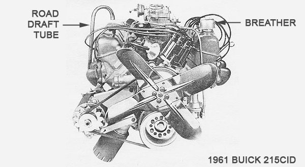
These problems led to development of the road tube which was very effective, �
resulted in much cleaner engine compartments and cleaner air for the driver and �
passengers. It diverted the objectionable fumes and oil spray down under the car �
and was a significant advance. The downside was that the oil vapors were now �
deposited on the road surface, leaving a wide, dark oily swath between the two �
tire tracks of public roads.�
�
�
�
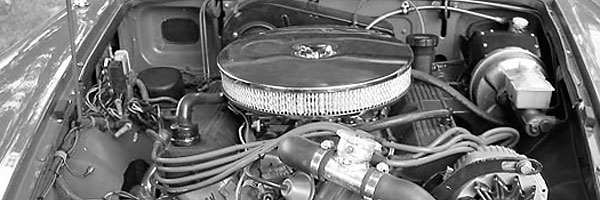
It was soon discovered that by cutting the end of the road draft tube at an angle �
and extending it into the airstream below the car an actual flow of fresh air could �
be created through the engine by providing an inlet breather, often in the form of �
an oil filler cap with a coarse mesh filter material, which acted as a flame arrestor �
and kept bugs out of the crankcase. A similar mesh in the road tube (sometimes placed �
inside the engine) served the same purpose on the other end. This new development �
was highly touted as an advancement which increased both engine life and oil change �
intervals by removing combustion byproducts quickly before they could combine with �
the crankcase oil and form acids, sludge, and other harmful and non-lubricating �
contaminants. �
�
This insight ultimately led to the development of the modern PCV system as we know �
it today. Various schemes were tried in order to find new ways of evacuating gasses �
from the crankcase, but what most had in common was that they relied on some means �
of suction to do the job. This generally meant the use of manifold vacuum as the most �
practical method. For us this means two things: firstly that most PCV systems are �
pretty consistent, and secondly that other alternative methods are possible.�
�
�
�
The usual PCV systems come in two basic flavors, and I'll distinguish them here by �
referring to them as American and British respectively, due to the prevalence of �
their use by manufacturers in each country, and in particular in distinguishing �
LBC's from Detroit iron. �
�
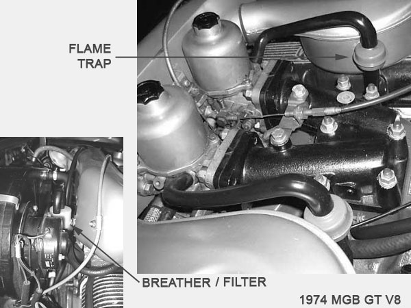
In the British system, which is the more straightforward of the two, manifold vacuum �
is plumbed directly to the crankcase using a 0.5" or 0.75" diameter line. An orifice �
of typically 0.030" or less is provided on a line feeding fresh air into the crankcase. �
Sometimes this line draws vapors from a vapor recovery canister as well, thereby purging �
the canister and feeding those vapors indirectly into the engine intake, and sometimes �
this orifice is contained in an oil filler cap, but for the purposes of PCV it functions �
the same either way. It does however have the potential to either enrich or lean the �
idle mixture to a limited degree. The manifold vacuum purges the crankcase of blowby �
fumes. By placing the crankcase under vacuum, a metered quantity of fresh air is �
drawn into the crankcase through the orifice... at least at idle and part throttle. �
As the throttle opens and engine load increase, blowby also increases proportionally �
until at some point the crankcase transitions from vacuum to positive pressure. This �
may not occur with a new engine in good condition using a larger vacuum line, but �
it certainly will with an engine having significant mileage. When the crankcase is at �
positive pressure, nothing changes on the vacuum side other than the volume of gasses �
going into the intake, but on the orifice side the flow reverses. This is usually not �
particularly significant due to the small size, but can contaminate the carbon in the �
vacuum canister over the course of time.�
�
Enjoying this article? Our magazine is funded through the generous support of readers like you!
�
To contribute to our operating budget, please click here and follow the instructions.
�
(Suggested contribution is twenty bucks per year. Feel free to give more!)�
�
American systems use a large diameter vent line to the atmosphere, usually running �
from a valve cover to a location in the air filter housing, and a smaller diameter �
line to the intake manifold, usually 0.3125" to 0.375" in diameter. This system �
restricts the amount of combustible air which enters the engine with a PCV valve �
rather than an orifice, and it is placed in this intake line. The PCV valve is pretty �
unique in that it allows full flow at low pressure differentials across the valve �
and a metered restriction above that level. It also shuts off flow in the reverse �
direction, thereby eliminating the need for a flame trap. This is done by using a �
shuttle inside the valve which I'll return to shortly, as this is the most misunderstood �
part of the system. �
�
The crankcase is never under vacuum but can become slightly pressurized. The large �
diameter vent line allows fresh air into the crankcase and also allows excess blowby �
to vent into the air cleaner housing through a flame arrestor where they are ingested �
by the engine, whenever engine loads and throttle openings are great. Under part �
throttle the PCV valve is open due to the lower vacuum applied across it and the �
lower level of blowby so most if not all of the blowby is sucked into the intake, �
drawing fresh air into the engine in the process and also tending to lean out the �
intake mixture during cruise. During idle there is enough vacuum to shuttle the �
PCV valve to the metered position and there is usually very little blowby so most �
of that is ingested along with a small amount of fresh air which is accounted for �
by adjustment of the idle mixture screws. This is one reason the idle mixture has �
to be adjusted as the rings wear. Under heavy throttle, although the level of �
vacuum drops to near zero, should the level of blowby become great enough the �
shuttle will shut down the flow to the metered level, diverting most of the blowby �
to the air cleaner and ingesting only a metered amount of blowby through the PCV �
valve. �
�
The effect of routing these gasses through the air cleaner is to enrich �
the intake mixture proportionally because the carb doesn't know the difference �
between fresh air and recycled combustion by-products. So it is interesting that �
the PCV system helps to give us a lean cruise and a rich WOT, but there is little �
or no correlation between PCV, carburetor, and volume of blowby other than the �
initial calibrations of the carb and PCV valve and no mechanism to account for �
engine wear other than the shuttle valve and idle mixture screws. The interesting �
thing about this is that the same PCV system is still in use with very little �
modification on our newer fuel injected engines, although they do have a feedback �
mechanism in the form of an oxygen sensor.�
�
These systems work quite well normally, but things tend to get interesting �
once performance modifications are made. Often the PCV systems are unintentionally �
modified to the point that they can no longer function properly, and this is �
particularly common with aftermarket intakes, air filters, valve covers, forced �
induction and the like. It is still possible on almost any performance engine �
to design and tune for a PCV system that works properly and this is especially �
important in a street driven car. For all out performance it is less of a �
consideration and in fact the blowby fumes do dilute the intake charge somewhat, �
so in these cases a simple crankcase vent is often used, harking back to the early �
days, with all their attendant inconveniences. Often modifications are made to the �
system unintentionally, in the quest for more performance and a better appearance, �
and this can result in problems. One of the most bothersome is pressurization of �
the crankcase, with symptoms of excess oil sprayed about the engine compartment �
in various places as it is forced past gaskets and seals. Another is the chance �
of a crankcase explosion should the need for a flame trap be overlooked. Then of �
course, any improperly functioning system will have a need for more frequent oil �
changes, as the combustion byproducts contaminate the oil more rapidly.�
�
For your street driven car there are answers. Sometimes the British system is �
more appropriate, and sometimes American, but it's best to keep in mind how each �
one operates and not try to mix the two. When fitting an open element air cleaner �
onto a typical American 4-barrel carbureted V8, for instance, it's quite easy to �
install the vent line to the base of the air cleaner inside the element, thereby �
keeping the system intact. Things aren't quite so neat and clean when fitting a �
similar air cleaner on a Rover V8, because Rover engines were originally set up �
with an orifice-type system. Some of these are easily changed over and some are �
not, depending on the fittings on the rocker covers. Bear in mind that the large �
vent line of 0.625" or possibly 0.75" in some cases cannot be replaced with a �
0.375" hose, or even two of them. Flow increases by the square of the diameter, �
meaning that a 2" pipe flows four times as much as a 1" pipe. So you would need �
four 0.375" lines to match one 0.75" line. If your valvecovers do not have the �
proper fittings and you are not willing to add larger ones to them then you may �
need a larger line to the crankcase in an alternate location. Early SBC's had a �
vent line that went through the block web behind the intake manifold. A large �
diameter tube rising from the pan may be another option. You might use the �
mechanical fuel pump mounting boss. Or you may be able to use the orifice system, �
bearing in mind that using smaller lines will cause it to operate under pressure �
more than it might otherwise. This may require recalibration of your carburetor �
due to the differences mentioned above, or it may be possible to find a suitable �
carburetor calibrated for the orifice system, since some British cars were �
available with a four barrel carburetor. There are other cases where an orifice �
system is a good choice, such as any induction system where the throttle body is �
at the inlet of the system. This might be the case with an IR setup or where an �
engine is supercharged. In these situations there is no practical way to locate �
the vent tube, and therefore no way to ingest the excess blowby fumes. The solution �
is to port the crankcase to manifold vacuum (or inlet vacuum in the case of a �
blower) and use the orifice to restrict flow into the crankcase and subsequent �
leaning of the intake mixture. It is worth noting here that often EFI systems �
take control of the PCV system, such as by including a purge valve for the �
emissions canister, allowing options such as pulling fresh air in at idle to give �
more precise control of the mixture. Some of these systems may be able to divert �
PCV intake on WOT for maximum power output. WARNING: All lines from crankcase to �
intake system must have some form of flame arrester! To overlook this is to invite �
a crankcase explosion, which in the best possible scenario will have you replacing �
your lifter valley pan.�
�
Finally, we have the alternative systems, the most familiar being the collector �
scavenger tube. These are really not suitable for a street driven application �
because of two things: mufflers, and the fact that they do not work well at idle. �
For racing it's a good idea, but once you add the restriction of a muffler you �
have created backpressure which will reverse the flow in the scavenger tube and �
make the system ineffective. Another option is an external scavenger pump. These �
tend to be a more complicated solution, but are another possibility that may �
have merit in special situations. Theoretically it would be possible to evacuate �
the crankcase using positive pressure and this would tend to lead to seal problems, �
but if those woes were overcome one might even find a way to route forced induction �
through the crankcase on its way to the cylinder, provided an adequate air/oil �
separator were designed. Two stroke engines inherently use this principle, simply �
burning the oil as they go.�
�
So that's the basic lowdown. No doubt there are details that I've left out but �
it's enough to give the average person the picture. Hopefully it's enough to help �
sort through the tangled mess and maze of confusion that typically surrounds �
these systems.�
� Disclaimer: This page was researched and written by Jim Blackwood. Views expressed � are those of the author, and are provided without warrantee or guarantee. Apply at your � own risk.�