
�
�
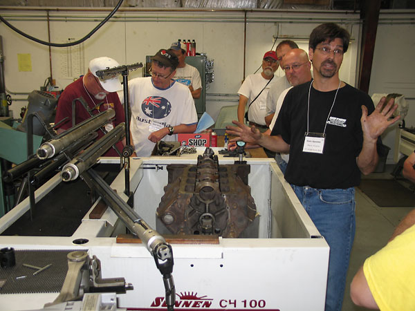
Dale Spooner's Motion Machine machine shop in Danville Virginia
� �� by: Larry Shimp�
��
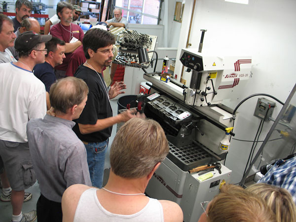
During BritishV8 2009, we took a group tour of Dale Spooner's Motion Motion �
automotive machine shop. This shop has state of the art equipment capable of �
producing the fine tolerances needed to build reliable racing engines. Extra �
precision may not be as important in a street engine, but it doesn't hurt either.�
�
Dale prepared demonstrations of each of the major types of machining operations �
to show just what is involved. Hopefully, the information will help us to evaluate �
local machine shops before trusting our engines to them. Of course, engines and �
parts can always be sent to Dale.�
�
In addition to the machining demonstrations, coffee and pastries we served at the �
start followed by a hot lunch at the end. It was a very well spent morning.�
�
The following snapshots show just a portion of what we saw and discussed.�
�
Crankshaft
��
�
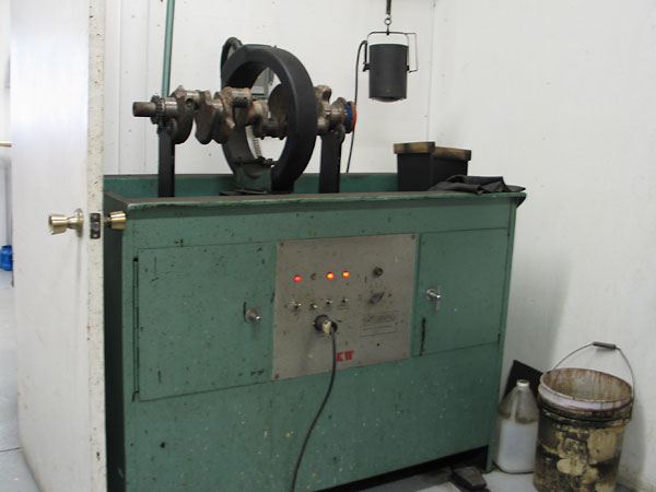
The Magnaflux machine is used to check for cracks. Its coil is magnetized and moved over the item
�
to be checked (such as a crankshaft, as shown here). Magnetic powder collects at cracks because
�
the cracks disrupt the induced magnetic field in the object. This only works on ferritic materials
�
Non-magnetic materials like aluminum must be checked with other methods, such as "Zyglo".
�
�
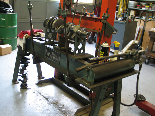
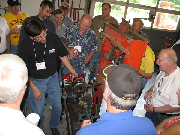
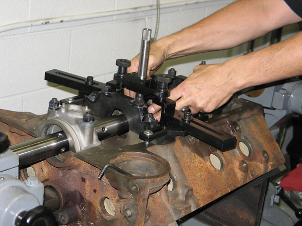
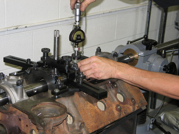
Winona Van Norman crankshaft checking and straightening fixture, with bent crankshaft in place.
�
�
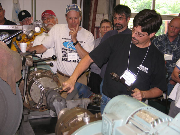
Turning shaft to measure "wobble". A badly bent shaft will turn hard or unevenly in an engine. This can
�
be checked with the main bearings bolted down and the rods not attached. Another cause for these
�
symptoms is misaligned main bearing bores. Even if the crankshaft turns freely, it should be checked
�
anyway because there could be minor bending that is accommodated by the bearing clearances.
�
�
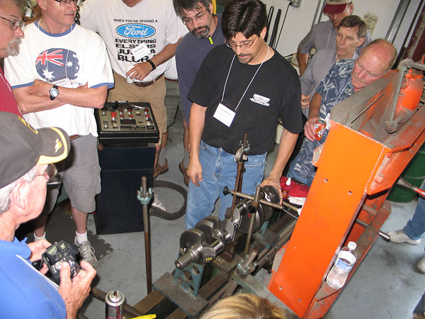
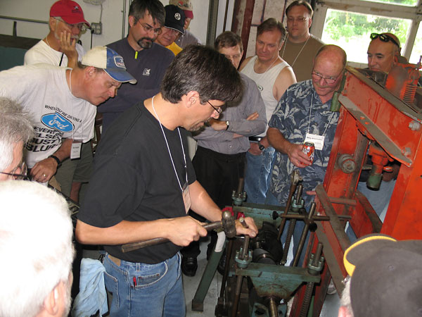
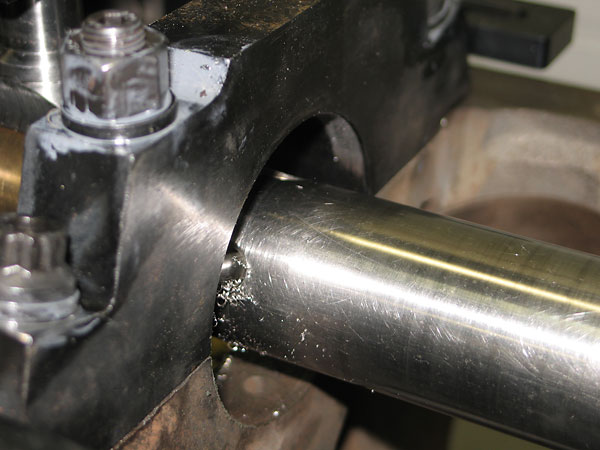
Putting the high spot on top.
�
�
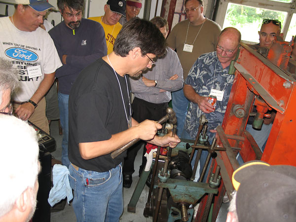
Hitting the high spot with a hammer and drift to straighten the crankshaft.
�
�
Another view of hammering on the high spot. After one round of hammering, the crank was within a few
�
thousandths of straightness. At this point, it could possibly have been installed and used, except that
�
this particular crank had severely damaged journals due to previously spun bearings and a thrown rod.
�
�
�
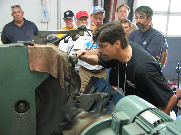
Crankshaft mounted on the Winona Van Norman CG250 crankshaft grinder.
�
�
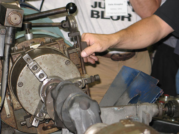
Indexing chuck. This chuck allows the rod journals to be moved to the center of rotation
�
of the lathe. The offset distance and degrees of rotation can be precisely controlled to
�
bring the journals into precise alignment, and even-out the stroke on all cylinders.
�
�
Grinding the crankshaft's bearing journals.
�
�
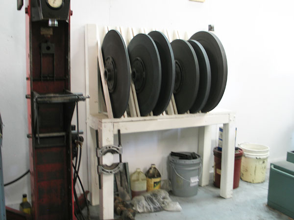
A variety of grinding wheels are needed to suit various widths of crankshaft bearing journals.
�
�
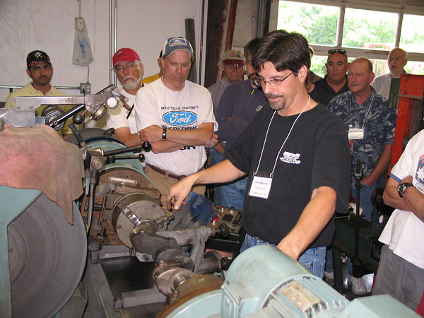
Journals are further polished using very fine abrasive belts.
�
�
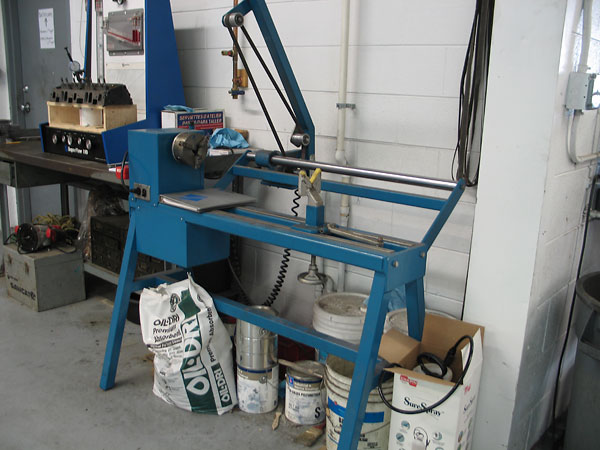
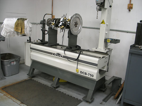
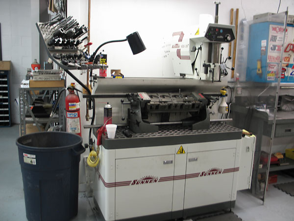
Sunnen DCB-750 computerized digital crankshaft balancer.
�
The crankshaft and flywheel are installed with weights that duplicate the
�
combined rod-and-piston weights. It works like a wheel/tire balancing machine.
�
�
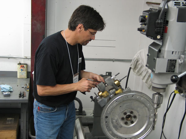
Oiling a journal under a weight assembly. The weights remain in vertical alignment while the crankshaft turns.
�
| �
Enjoying this article? Our magazine is funded through the generous support of readers like you! � To contribute to our operating budget, please click here and follow the instructions. � (Suggested contribution is twenty bucks per year. Feel free to give more!)� |
�
Engine Block
��
�
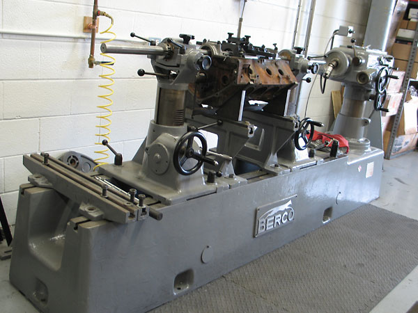
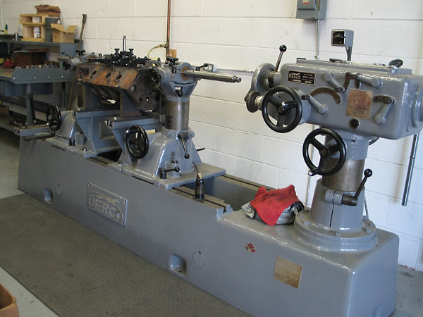
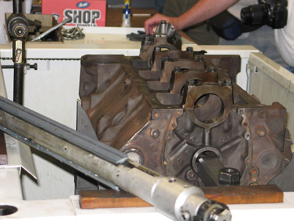
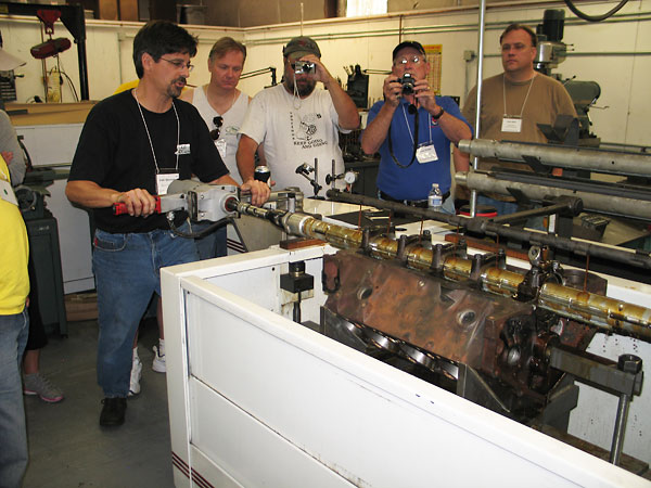
Engine block work starts with line boring or align honing because the set-up for
�
other machining operations reference the bearing journals. They need to be accurate!
�
This is a Berco S.p.A. (Italian) line boring machine.
�
�
An engine block has been mounted on the line boring machine. The boring bar is in place, ready to be
�
connected to the boring drive head.
�
�
Close-up view of main bearing cap that is to be bored to match the seat already in the block.
�
Boring bar guides are in place.
�
�
Measuring alignment.
�
�
Close-up view of bearing cap being bored.
�
�
Sunnen CH100 align honing machine can be used instead of the line boring machine if the bearing
�
seats aren't badly misaligned, or for putting a final finish on bearing seats after boring.
�
Honing bars self-center themselves in the bearing journals.
�
�
Close-up view of the honing stone.
�
�
Bearing seats being honed.
�
�
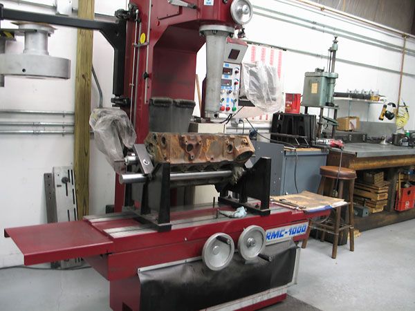
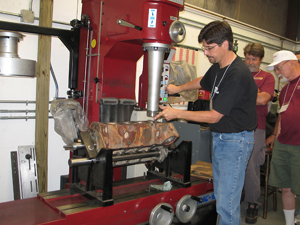
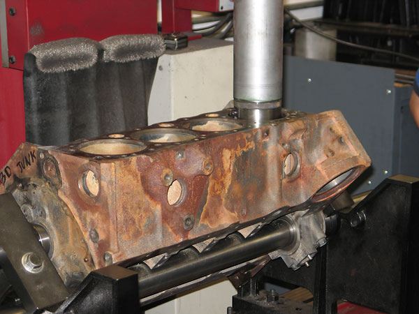
RMC-1000 cylinder boring machine with power column, auto table feed, and electronic bore centering.
�
�
Another view, showing close up of boring bar.
�
�
Cylinder boring operation in progress.
�
�
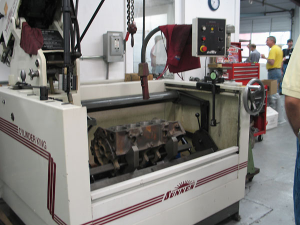
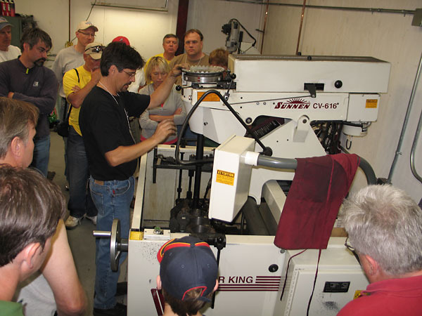
Sunnen CV-616 Cylinder King vertical honing machine. Honing is carried out after boring to provide
�
the final finish. The finish varies depending on the type of piston rings being used.
�
�
Cylinder honing in process.
�
Cylinder Head and Valves
��
�
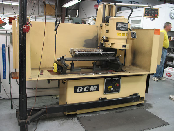
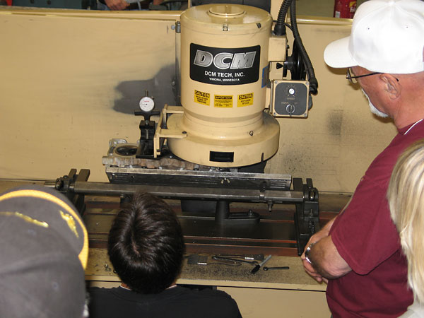
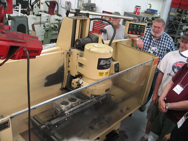
DCM Tech surface grinder. Surfacing a head removes warpage and "slope".
�
�
Measuring the slope of the cylinder head.
�
�
Surfacing in progress.
�
�
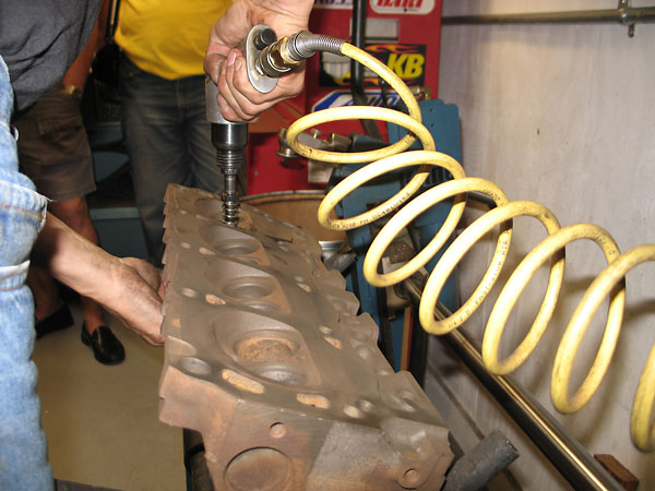
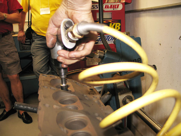
Boring valve guides. This head has cast in valve guides that must be bored out for a liner to be
�
inserted that will to correct the guide wear. An alternative is to bore the guides out even more
�
and put new guides in, but the liners actually work better. In this operation, the head is held
�
in a fixture and the boring tool is guided by another fixture on the machine bench.
�
�
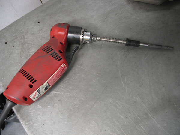
Close-up view of the valve guide boring tool, powered by an ordinary Milwaukee drill motor.
�
�
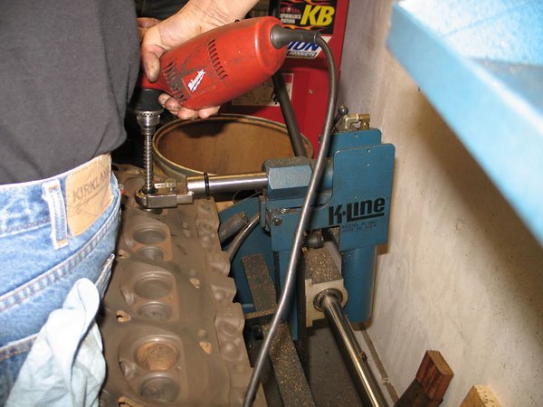
Some machine shops knurl worn valve guides to reduce clearances. Dale warned us that this is a poor idea;
�
if it works at all, it only lasts a few thousand miles. To repair the guides, Dale recommends thin-wall
�
phospher bronze liners be inserted and honed to correct guide wear as illustrated here.
�
�
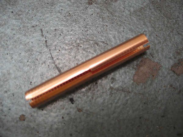
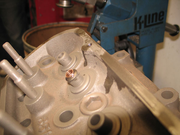
K-Line interrupted spiral guide-liners as supplied, ready to use.
�
�
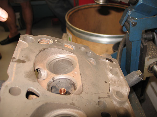
Valve guide liner pressed in place. It now needs burnishing to its final diameter.
�
�
Valve liner burnishing operation, in process.
�
�
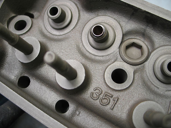
Finished guide, ready to cut to length with a special tool.
�
�
�
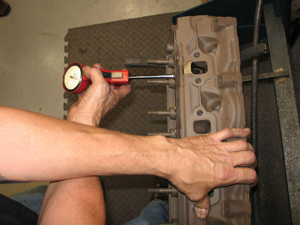
Checking guide bore. It should have a slight taper to account for differential thermal
�
expansion when the engine is operating.
�
�
Finished!
�
�
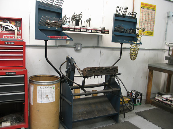
General view of valve guide bench.
�
�
Sunnen VGS-20 valve guide and seat machine. The valve guides must be machined first because they
�
define the position of the valves.
�
�
Valve seat grinding, using valve guide as the reference point. Various cutters are used
�
to give multi-angle valve seats. Three-angle seats are good; five angle are better.
�
The graduated angles help to improve gas flow through the seat area.
�
� Photos by Curtis Jacobson for BritishV8 Magazine. All rights reserved.�