
�
� by: Larry Shimp�
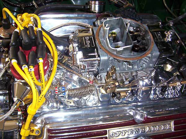
� There is no doubt that fuel injection will give the optimum results, but a properly � set up carburetor actually works quite well. The key is "properly set up".�
� Float bowl and float setting�
� From my experience, the most important factor in carburetor selection is float bowl � design. The fuel float is intended to keep the fuel at a constant level within the � float bowl which permits the proper functioning of all of the fuel circuits. With � an incorrect or fluctuating float level, a carburetor cannot perform properly. When � the car is sitting and idling, any carburetor float/bowl works well. The key is what � happens when the car is moving, especially at the extreme performance limits � possible with a V8 powered MGB.�
� There are two basic float designs: center hung and side hung. Side hung means the � pivot axis of the float is parallel to the direction of travel. Center hung means � that the pivot axis is perpendicular to the direction of travel. Side hung floats � tend to get upset on hard cornering. The float on the outside of the corner tends to � stay closed, letting the fuel level drop, while the inner float tends to open, � raising the fuel level. The result is an unequal, sub-optimum fuel mixture that � differs on each side of the carburetor, leading to poor throttle response and a � lower power output. Holley carburetors can be either side or center hung, but all � Carter carburetors are center hung. However, because the Carter float bowls are on � either side of the carburetor, they behave more like side hung floats. I first had � a Carter carburetor on my car, and experienced poor throttle response on hard � cornering. I could find no fix, so I went to a center hung Holley.�
�
�
�
 �
�
Performance Carburetor Selection and Set Up
� The British V8 Newsletter, Volume XV Issue 1�� by: Larry Shimp�
� There is no doubt that fuel injection will give the optimum results, but a properly � set up carburetor actually works quite well. The key is "properly set up".�
� Float bowl and float setting�
� From my experience, the most important factor in carburetor selection is float bowl � design. The fuel float is intended to keep the fuel at a constant level within the � float bowl which permits the proper functioning of all of the fuel circuits. With � an incorrect or fluctuating float level, a carburetor cannot perform properly. When � the car is sitting and idling, any carburetor float/bowl works well. The key is what � happens when the car is moving, especially at the extreme performance limits � possible with a V8 powered MGB.�
� There are two basic float designs: center hung and side hung. Side hung means the � pivot axis of the float is parallel to the direction of travel. Center hung means � that the pivot axis is perpendicular to the direction of travel. Side hung floats � tend to get upset on hard cornering. The float on the outside of the corner tends to � stay closed, letting the fuel level drop, while the inner float tends to open, � raising the fuel level. The result is an unequal, sub-optimum fuel mixture that � differs on each side of the carburetor, leading to poor throttle response and a � lower power output. Holley carburetors can be either side or center hung, but all � Carter carburetors are center hung. However, because the Carter float bowls are on � either side of the carburetor, they behave more like side hung floats. I first had � a Carter carburetor on my car, and experienced poor throttle response on hard � cornering. I could find no fix, so I went to a center hung Holley.�

�
The Holley center-hung design completely solved the cornering problem. However, �
there were some straight line effects that did not show up with the Carter. The �
most obvious was that the engine would flood and stall on hard braking. The cause �
was that the fuel in the rear (secondary) fuel bowl would slosh up the vent tube �
and into the carburetor throat. Holley sells a vent tube modification kit that �
moves the vent intake from the area by the throat to the outer edge of the float �
bowl (Summit part number HLY-26-89). This prevents any fuel slosh out of the vent �
from either bowl on either acceleration or braking. I highly recommend this �
modification, it solved the problem I had with the engine flooding out and stalling �
upon hard braking. Installing the vent is easy, but it does require a #51 drill bit �
to drill a small hole for a rivet/screw using the locating dimple in the metering �
plate body. (If you have a holley carburetor model without a secondary metering plate, �
this modification probably won't fit.) The #51 drill is available from Micro Mark �
and similar hobby suppliers. An alternative to the vent extensions is made by Moroso �
(Summit part number MOR-65221) which puts a foam baffle in the front of the bowl. �
However, it requires that the bowls be moved out with a spacer and thus it changes �
the spacing of the fuel inlets.�
��
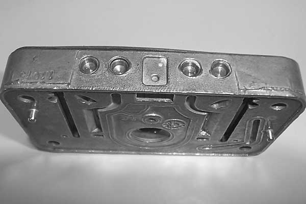
� Metering Block (note the dimple that has to be drilled out for screw/rivet)
�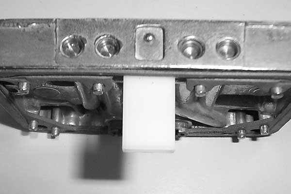
� Vent Extension in Place
�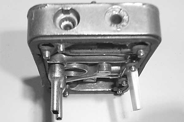
� Vent Extension and Mr. Gasket Jetty Extensions� �
� Another potential problem with the in-line holley fuel bowls is that the fuel in � the secondary bowl can move to the rear under hard acceleration, partially starving � the secondary jets. The fix for this is a kit that consists of a pair of jet � extension tubes that move jets to the rear of the float bowl, and a notched float � to clear the jet extensions (Summit part number HLY-116-19), or a kit by Mr Gasket � (Summit part number MRG-6060) that consists of a pair of flattened sheet metal jet � extensions that can be used with the standard plastic float. (Some carburetors come � with a brass float, and this may be too large to work with the jet extensions.) � Holley also makes plastic extensions (Summit part number HLY-55009HOL) that do � not seem to need a notched float (but probably need a plastic float). Jet extensions � are probably not necessary even on a very fast MGB because the drop in fuel level � should be compensated for by new fuel entering the carburetor. It makes more sense � for big block engines with 1000 cfm carburetors that use huge quantities of fuel � during acceleration. However, it does not hurt to install the kit. �
� The next item to consider is the needle valve itself. The needle valve is held � closed by float pressure once the bowl is full, but it must be able to flow very � freely once the float level drops a small amount to facilitate keeping fuel level � constant during periods of high fuel demand. A metal seat and needle is usually � standard, but vibration, vehicle acceleration, and bumps can cause momentary � unseating. When vibration causes the valve to bounce, running fuel level will � be above the resting fuel level. A remedy for this is a needle with a rubber tip � that is more tolerant of vibration and vehicle acceleration.�
� Naturally, all of the above steps are useless if the initial float level is incorrect. � With a Holley, the float level is normally adjusted externally to the height of an � inspection hole in the side of the float chamber. The best way to do this is with � the engine off and the electric pump on. Holley (and others) make clear plastic plugs � to replace the metal bowl plugs, but the plastic plugs cannot be left in permanently � because gasoline will eventually attack them. Holley also offers replacement bowls � with glass windows, but these are not really necessary. Some old Holley two barrel � carburetors even had float chambers made entirely of glass. It was a neat idea, but � that concept is long gone.�
� Remember that Holley has a long tradition in road racing competition, including � Le Mans. Their success would not have been possible if the float levels were constantly � being upset by acceleration, braking, and cornering! �
�
�
�
�
� Metering Block (note the dimple that has to be drilled out for screw/rivet)
�
� Vent Extension in Place
�
� Vent Extension and Mr. Gasket Jetty Extensions�
� Another potential problem with the in-line holley fuel bowls is that the fuel in � the secondary bowl can move to the rear under hard acceleration, partially starving � the secondary jets. The fix for this is a kit that consists of a pair of jet � extension tubes that move jets to the rear of the float bowl, and a notched float � to clear the jet extensions (Summit part number HLY-116-19), or a kit by Mr Gasket � (Summit part number MRG-6060) that consists of a pair of flattened sheet metal jet � extensions that can be used with the standard plastic float. (Some carburetors come � with a brass float, and this may be too large to work with the jet extensions.) � Holley also makes plastic extensions (Summit part number HLY-55009HOL) that do � not seem to need a notched float (but probably need a plastic float). Jet extensions � are probably not necessary even on a very fast MGB because the drop in fuel level � should be compensated for by new fuel entering the carburetor. It makes more sense � for big block engines with 1000 cfm carburetors that use huge quantities of fuel � during acceleration. However, it does not hurt to install the kit. �
� The next item to consider is the needle valve itself. The needle valve is held � closed by float pressure once the bowl is full, but it must be able to flow very � freely once the float level drops a small amount to facilitate keeping fuel level � constant during periods of high fuel demand. A metal seat and needle is usually � standard, but vibration, vehicle acceleration, and bumps can cause momentary � unseating. When vibration causes the valve to bounce, running fuel level will � be above the resting fuel level. A remedy for this is a needle with a rubber tip � that is more tolerant of vibration and vehicle acceleration.�
� Naturally, all of the above steps are useless if the initial float level is incorrect. � With a Holley, the float level is normally adjusted externally to the height of an � inspection hole in the side of the float chamber. The best way to do this is with � the engine off and the electric pump on. Holley (and others) make clear plastic plugs � to replace the metal bowl plugs, but the plastic plugs cannot be left in permanently � because gasoline will eventually attack them. Holley also offers replacement bowls � with glass windows, but these are not really necessary. Some old Holley two barrel � carburetors even had float chambers made entirely of glass. It was a neat idea, but � that concept is long gone.�
� Remember that Holley has a long tradition in road racing competition, including � Le Mans. Their success would not have been possible if the float levels were constantly � being upset by acceleration, braking, and cornering! �
�
�
Fuel pump and lines�
� The final factor in maintaining proper float bowl levels is the fuel pump. Fuel pumps � are rated on a gallon per hour basis, and even the smallest pump would seem adequate � for an MGB V8 (after all, no-one uses 20 gallons of fuel per hour). However, in � reality, a fuel capacity of at least 75 gallons per hour is necessary to be able to � provide enough fuel during high demand acceleration conditions. In general, no fuel � pump meant for a 4 cylinder MGB is satisfactory for a V8 MGB because of the much � higher momentary fuel consumption possible with a V8. �
� The pump pressure is also important. Most carburetors are set up to work with 5 to � 7 psi. Higher pressure forces open the float valves, and lower pressure cannot keep � the level constant under high acceleration. (The pressure needed to force the fuel � forward from the fuel tank under rapid acceleration also plays a role in this.) Pumps � with a capacity of 150 to 200 gallons per hour or more often have pressures in excess � of 7 psi, and therefore need a pressure regulator. However, a 5 to 7 psi rated pump � can be found with a flow of around 100 gallons per minute that will be satisfactory.�
� Electric fuel pumps can be noisy. I have tried pumps manufactured by Carter, Holley, � and Mallory. The first two were intolerably noisy, even with rubber isolation mounts. � The Mallory is very quiet, and I strongly prefer it for that reason. �
� With an electric fuel pump, in the event of an accident, fuel can be pumped from a � broken fuel line at a high rate and lead to a serious fire hazard. Do not install � an electric pump without some type of automatic emergency cut off! I used a standard � late model MGB inertia switch. Other inertia switches are available. There are also � schemes that use a oil pressure switch that cut off the pump when the oil pressure � drops to zero. Whatever system you use, be sure you understand how to install it or � have someone who does install it.�
� The best pump location is back by the fuel tank, where MG originally put it. This � keeps the fuel line pressurized and so prevents problems from vapor lock. Put a fuel � filter before the pump. This will protect the high speed, precision, moving pump � parts from damage from debris. And, of course, follow all of the pump manufacturer's � instructions and recommendations.�
� The fuel line should be 3/8 inch in diameter. Smaller sizes may restrict fuel flow. � Use steel line, not rubber line. Rubber hoses should be restricted only to the ends � of the line where it joins the pump and carburetor. Be sure to route and clip rubber � fuel lines to avoid chaffing or pinching damage. (Give a thought to how vehicle � components are likely to shift in an accident.) The metal pipes where the rubber � hoses connect should have proper beads to help retain the hoses. �
� Tuning principles�
� All of the above preparations (in addition to making sure the ignition system is � properly set up) need to be carried out before tuning the carburetor. That way, � tuning will only be affected by the carburetor settings themselves. With external � influences, tuning will be impossible. �
� The following tuning recommendations are most applicable to Holley carburetors. � Carter and other carburetors may work on different principles. Much has been written � about carburetor tuning, so I will concentrate on issues that are especially relevant � to a street tuned MGB V8. To begin, there are two basic carburetor types: those with � vacuum secondaries and those with mechanical secondaries. For small block street � engines, vacuum secondaries make the most sense and there is (in my opinion) no � reason to consider mechanical secondaries. The vacuum secondary carburetors have � the advantage that they are inherently very adaptable to a wide range of engine sizes � and states of tune, while a mechanical secondary carburetor must be carefully matched � to the engine as far as flow capacity is concerned.�
� Any carburetor has three types of fuel circuits: idle, transition, and power (main). � Most cruising is on the transition circuit, which is the hardest to tune. Idle is � adjusted by the idle jets, and power by the main jets. Transition behavior is mainly � governed by fixed air and fuel bleeds that can only be modified by custom fabrication � or expensive aftermarket metering blocks. My advice is to find a carburetor that � naturally has the "right" transition settings for the engine. Holley has a huge number � of carburetor models to choose from, and I have only tried a few. Basically, I have � found that the Street Avenger 670 (Summit part number ???????) has excellent � characteristics for my Ford 302 crate engine. I also tried the Street Avenger 570 � which would seem to be better sized, but the transition circuits were too far off. � I also tried various Demon carburetors, including one that was supposed to be perfectly � set up for the Ford crate engine, but none were even close. (Luckily with eBay it's � possible to buy and sell a bunch of carburetors without spending too much money.) �
��
�
� To assess the carburetors, I used a wide band air/fuel meter installed in the exhaust � so I could monitor the mixture while driving. There are traditional ways of tuning � such as timing acceleration runs and shutting off the engine at full throttle, then � coasting to a stop and checking the plug deposits, but these are not very practical � on public roads. Dyno tuning works, but an hour of dyno time can cost over $100, and � many sessions may be needed. Therefore the approximate $250 cost of an air/fuel meter � seems reasonable. �
� The goal with the transition circuits is to achieve an air/fuel ratio during cruise � of 14 or 15 to 1. Then, upon the slightest throttle opening, the ratio should � immediately increase to 11 to 12 to 1 to prevent hesitation. With some carburetors, � the transition mixture was very rich (giving poor fuel economy), then went dead � lean upon opening the throttle. The only cure for the leanness was very large main � jets that resulted in much too rich of a full throttle mixture. I gave up on these � carburetors. Note: these results were obtained with small, slow throttle movements � that should not involve any accelerator pump action, so increasing the accelerator � pump jet size did not help. �
�
�
�
� The final factor in maintaining proper float bowl levels is the fuel pump. Fuel pumps � are rated on a gallon per hour basis, and even the smallest pump would seem adequate � for an MGB V8 (after all, no-one uses 20 gallons of fuel per hour). However, in � reality, a fuel capacity of at least 75 gallons per hour is necessary to be able to � provide enough fuel during high demand acceleration conditions. In general, no fuel � pump meant for a 4 cylinder MGB is satisfactory for a V8 MGB because of the much � higher momentary fuel consumption possible with a V8. �
� The pump pressure is also important. Most carburetors are set up to work with 5 to � 7 psi. Higher pressure forces open the float valves, and lower pressure cannot keep � the level constant under high acceleration. (The pressure needed to force the fuel � forward from the fuel tank under rapid acceleration also plays a role in this.) Pumps � with a capacity of 150 to 200 gallons per hour or more often have pressures in excess � of 7 psi, and therefore need a pressure regulator. However, a 5 to 7 psi rated pump � can be found with a flow of around 100 gallons per minute that will be satisfactory.�
� Electric fuel pumps can be noisy. I have tried pumps manufactured by Carter, Holley, � and Mallory. The first two were intolerably noisy, even with rubber isolation mounts. � The Mallory is very quiet, and I strongly prefer it for that reason. �
� With an electric fuel pump, in the event of an accident, fuel can be pumped from a � broken fuel line at a high rate and lead to a serious fire hazard. Do not install � an electric pump without some type of automatic emergency cut off! I used a standard � late model MGB inertia switch. Other inertia switches are available. There are also � schemes that use a oil pressure switch that cut off the pump when the oil pressure � drops to zero. Whatever system you use, be sure you understand how to install it or � have someone who does install it.�
� The best pump location is back by the fuel tank, where MG originally put it. This � keeps the fuel line pressurized and so prevents problems from vapor lock. Put a fuel � filter before the pump. This will protect the high speed, precision, moving pump � parts from damage from debris. And, of course, follow all of the pump manufacturer's � instructions and recommendations.�
� The fuel line should be 3/8 inch in diameter. Smaller sizes may restrict fuel flow. � Use steel line, not rubber line. Rubber hoses should be restricted only to the ends � of the line where it joins the pump and carburetor. Be sure to route and clip rubber � fuel lines to avoid chaffing or pinching damage. (Give a thought to how vehicle � components are likely to shift in an accident.) The metal pipes where the rubber � hoses connect should have proper beads to help retain the hoses. �
� Tuning principles�
� All of the above preparations (in addition to making sure the ignition system is � properly set up) need to be carried out before tuning the carburetor. That way, � tuning will only be affected by the carburetor settings themselves. With external � influences, tuning will be impossible. �
� The following tuning recommendations are most applicable to Holley carburetors. � Carter and other carburetors may work on different principles. Much has been written � about carburetor tuning, so I will concentrate on issues that are especially relevant � to a street tuned MGB V8. To begin, there are two basic carburetor types: those with � vacuum secondaries and those with mechanical secondaries. For small block street � engines, vacuum secondaries make the most sense and there is (in my opinion) no � reason to consider mechanical secondaries. The vacuum secondary carburetors have � the advantage that they are inherently very adaptable to a wide range of engine sizes � and states of tune, while a mechanical secondary carburetor must be carefully matched � to the engine as far as flow capacity is concerned.�
� Any carburetor has three types of fuel circuits: idle, transition, and power (main). � Most cruising is on the transition circuit, which is the hardest to tune. Idle is � adjusted by the idle jets, and power by the main jets. Transition behavior is mainly � governed by fixed air and fuel bleeds that can only be modified by custom fabrication � or expensive aftermarket metering blocks. My advice is to find a carburetor that � naturally has the "right" transition settings for the engine. Holley has a huge number � of carburetor models to choose from, and I have only tried a few. Basically, I have � found that the Street Avenger 670 (Summit part number ???????) has excellent � characteristics for my Ford 302 crate engine. I also tried the Street Avenger 570 � which would seem to be better sized, but the transition circuits were too far off. � I also tried various Demon carburetors, including one that was supposed to be perfectly � set up for the Ford crate engine, but none were even close. (Luckily with eBay it's � possible to buy and sell a bunch of carburetors without spending too much money.) �
�
| �
Enjoying this article? Our magazine is funded through the generous support of readers like you! � To contribute to our operating budget, please click here and follow the instructions. � (Suggested contribution is twenty bucks per year. Feel free to give more!)� |
� To assess the carburetors, I used a wide band air/fuel meter installed in the exhaust � so I could monitor the mixture while driving. There are traditional ways of tuning � such as timing acceleration runs and shutting off the engine at full throttle, then � coasting to a stop and checking the plug deposits, but these are not very practical � on public roads. Dyno tuning works, but an hour of dyno time can cost over $100, and � many sessions may be needed. Therefore the approximate $250 cost of an air/fuel meter � seems reasonable. �
� The goal with the transition circuits is to achieve an air/fuel ratio during cruise � of 14 or 15 to 1. Then, upon the slightest throttle opening, the ratio should � immediately increase to 11 to 12 to 1 to prevent hesitation. With some carburetors, � the transition mixture was very rich (giving poor fuel economy), then went dead � lean upon opening the throttle. The only cure for the leanness was very large main � jets that resulted in much too rich of a full throttle mixture. I gave up on these � carburetors. Note: these results were obtained with small, slow throttle movements � that should not involve any accelerator pump action, so increasing the accelerator � pump jet size did not help. �
�
�
The way to influence the richening upon small throttle movements is with the power �
valve, not the accelerator pump. The power valve is a vacuum operated valve that �
opens at high vacuum conditions to lean the mixture. It then closes as vacuum drops �
upon acceleration to richen the mixture. I have a relatively mild cam in my engine �
so I am using one of the highest rated power valves (closes at 10.5 inches of mercury). �
With a vacuum gauge I found my cruise vacuum is about 17 inches of mercury, so the �
power valve is open. Slight throttle opening drops the vacuum to 10 or less inches �
of mercury, and the power valve instantly closes and richens the mixture. Be aware �
that the standard power valve in the Holley Street Avengers is rated at about 6.5 �
inches of mercury, and so will be closed until relatively large throttle openings, �
unless you have a very radical cam that gives a low cruise vacuum. (Note: The power �
valve model number is equal to the value of the vacuum at which the valve closes.) �
This leads to a flat spot at small throttle openings and in most cases the standard �
power valve needs to be replaced. �
� Holley secondary metering systems don't normally have a power valve because the � secondaries only come into play at relatively low vacuum conditions. But without � the richening effect of the power valve, the secondary jet sizes need to be bigger � than the primary jet sizes. That's why Holley carburetors normally come with � secondary jets about 8 to 10 sizes bigger than the primary jets. If you buy a � used carburetor, always replace the power valve just to be sure, and check to see � what jets are installed.�
� Ignition timing�
� Ignition timing is also important to success with a lean cruise mixture, and a � vacuum advance distributor must be used. This will keep the timing well advanced � so the slow burning lean cruise mixture will fire properly. Then, as soon as the � throttle is opened slightly, the vacuum advance drops out, and the timing reverts � to a power setting. Without a vacuum advance, the engine will run poorly on a � lean mixture and will almost certainly hesitate with small throttle openings, � even with a properly chosen power valve. (My engine runs fine on a 15 to 1 � air/fuel ratio and gets about 26 mpg on the highway.)�
� Power valve protection�
� From my experience, one problem with power valves is that they can rupture from � a carburetor backfire. The Holley Street Avenger (and apparently all Holleys made � after about 1992) has a check valve that protects the power valve in the event � of a backfire so it's not a problem with this model series. There are also kits � made by several manufacturers to retrofit older Holley carburetors with the check � valve. I highly recommend this modification. �
� Jetting and secondary vacuum canister springs�
� With the carburetor properly set up and the right power valve installed, final � tuning is relatively very simple. The goal is smooth throttle response with no � surging or flat spots associated with rapid throttle openings. If throttle � response is good, chances are that the full throttle mixture will be reasonably � correct as well. First of all, if there is some hesitation upon throttle opening � at low engine speeds, it is probably the accelerator pump circuit. Holley a has � a number of accelerator pump cams and even a larger capacity accelerator pump � itself (50 cc versus 30 cc). I have found that simply putting in the next size � larger accelerator pump jets (0.033 inches versus 0.030 inches) worked fine � for my car. �
� Throttle response�
� At higher speeds the secondary throttles open. When this occurs there should � be no surging, just a smooth increase in power. Some people think there should � be a surge as the secondaries open, but this only signifies a lack of power. � (A surge means either the engine was down on power until the secondaries opened � or there is a flat spot coming and going.) There is no accelerator pump � associated with the secondary throttles, the only tuning variables are primary � and secondary main jets, and the secondary vacuum capsule spring. If the primary � jets are too lean, there will be a surge as the richer secondary jets cut in. � On the other hand, if the secondary jets are too lean, there may be a flat spot � as the secondaries open. However, too soon of a secondary throttle opening will � also cause a flat spot even if the mixture is correct. This can be addressed by � putting a stiffer spring in the secondary vacuum capsule. For some reason, with � the Holley 570 carburetor, I had a flat spot when the secondaries opened even � though the eventual full throttle mixture was fine. Installing much richer � secondary and primary jets solved the flat spot, but the full throttle mixture � was then too rich. Fitting a stiffer spring in the vacuum capsule worked well, � but then the secondaries did not open all the way. For some reason the bigger � (670 cfm) carburetor works well with a softer vacuum capsule spring. (Note: � the degree of opening of the secondaries can be ascertained by putting a clip � on the secondary throttle rod. The clip will be pushed down the rod during � driving and give a record of how far the rod has moved. Be very careful that � the clip does not jam the throttle linkage and remove it immediately after the � test is finished! Note that the secondaries will never open when the engine is � revved up in neutral.) �
� There is a major difference between Holley and Edelbrock (Carter) carburetors in � when the vacuum secondaries come into action. With Edelbrock carburetors, the � secondaries are interlocked so that they cannot open until the primaries are � fully open. With Holley carburetors, there's no interlock and the secondaries can � open whenever primary vacuum gets sufficiently high. The Edelbrock interlock is � good for fuel economy because the secondaries never open unless the throttle is � floored. However, this can lead to sluggish part throttle response, especially � with the small primaries that Edelbrocks tend to have. The Holley allows the � secondaries to open under part throttle, high RPM conditions. This contributes � to a more responsive feel.�
��
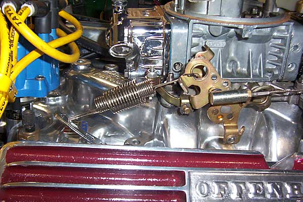
� Optimal Return Spring Orientation
�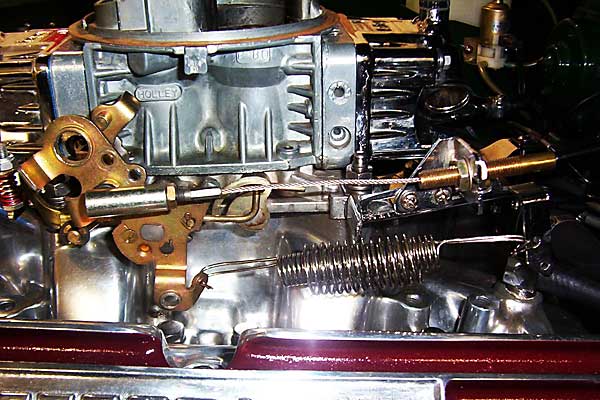
� Incorrect Spring Position� �
� Throttle linkage�
� Finally, make sure the throttle is opening fully. This is an area that is often � overlooked in carburetor set up, and it can cost a ton of power, I had to drill � an extra cable mounting hole in my carburetor throttle arm to get the right match � between the MGB accelerator and the carburetor. To check, with the engine off, � have someone push the throttle to the floor, and then see if you can open the � throttle at the carburetor any further. First be sure that the carburetor is � fully warmed up and the choke is off because some choke mechanisms limit the � throttle opening when cold. �
� For connecting a throttle cable, I recommend cable ball joints from � pegasusautoracing.com (either fixed, # 1276 or quick-disconnect, # 1274).�
� For safety, use dual throttle-return springs and make sure that at full-throttle � gas pedal movement is either limited by the floorboard or "pedal stop". The � carburetor-mounted linkage is NOT designed to withstand the load you can exert � with your leg muscles! Read the carburetor's manual for additional installation � recommendations.�
� The throttle return spring should be installed so that it directly opposes the � throttle cable, and not on the opposite side of the throttle shaft. A spring � connected to the opposite side of the throttle puts a load on the throttle shaft � as the cable pulls against the spring. This creates much more rapid wear in the � shaft and bushings which leads to air leaks that will cause an erratic idle and � a poor transition response. �
� Choke�
� A choke is not really needed with a manual transmission car, but it is a � convenience. An air cleaner is, however, essential. With limited hood clearance, � often all that will fit is a triangular foam air cleaner by Edelbrock. It is, � however, rather poor because it does not filter well, and can upset the flow � into the carburetor. An alternative that is almost as compact is the Mr. Gasket � dropped-base air cleaner, which really works much better except for one problem. � The top of this air cleaner is so low that it can interfere with the choke plate. � This is a consequence of the recess in the lid where the attaching nut goes. No � other drop case air cleaner has this recess, and it is the main reason why this � air cleaner fits under low hoods. I solved the choke interference problem by � simply removing the choke plate and shaft. I left the electric choke actuating � mechanism in place, as well as the rod that went to the choke shaft. The rod � and its plate seal what would otherwise be a hole that would let unfiltered air � into the carburetor. The choke mechanism still actuates the fast idle control, � and this is enough to make the engine livable, even down to zero degrees. The � air cleaner lid just touches the float bowl vent tubes. In the primary carburetor � side this looked like it might provide a restriction to air flow because of the � choke tower. I eventually cut off the choke tower, and it seemed to make a � difference in that the engine seems freer revving before the secondaries open � (but it could also be my imagination).�
��
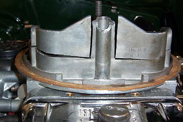
� Choke Tower Cuts
�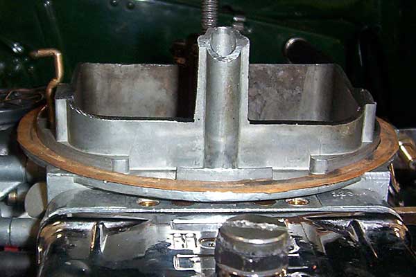
� Finished View of Modified Choke Tower
� �
� One other tip to gain space for the air cleaner is to have the carburetor � mounting flange angle milled to tilt the carburetor forward. Just a few degrees � will allow the air cleaner to follow the slope of the hood, and this does not � necessitate any change to the carburetor mounting studs. This is a tip I picked � up from Glen Towery. �
� Example settings�
� The optimum settings I found for my car are:
� Holley 670 street avenger
� Standard secondary spring
� Standard accelerator pump and cam
� 0.033" Accelerator pump jets
� 10.5 Power valve
� 58 primary jets
� 68 secondary jets �
� Your results may vary because different engines, cams, etc. will influence what � the optimum settings will be.�
� With the above settings my carburetor is "on the edge". This shows up as a � slight temperature sensitivity, where below about 40 degrees there is a slight � flat spot with small throttle openings (mainly in 5th gear below about 1800 rpm). � This gets slightly worse as the temperature goes lower, but even at zero degrees � it is still not bothersome. However, this is why car manufacturers adopted heated � air supplies to the carburetor with the advent of emissions controls.�
� A word about manifolds�
� There are several types of manifolds available including dual plane, single plane � and X type (or 360 degree type). One important property of these manifolds is the � plenum volume. A large plenum volume is needed for optimal high rpm power. � Mixture is drawn alternately from one side of the plenum and the other. The gas � develops an inertia as it flows, and this inertia makes flow reversals more � difficult. At high engine speeds the inertia problem is worse, and is one of the � reasons why high speed cams open earlier on the intake cycle than low speed cams. � A large plenum volume reduces the velocity of the gases in the plenum and so � minimizes the inertial problem. Performance type manifolds (single plane and X type) � already have large plenum volumes, but dual plane manifolds, because they are � not intended for all out performance engines, may or may not have decent plenum � volumes. �
� With an engine that has a mild cam and restrictive heads, such as a typical � 215 V8, plenum volume of any manifold is sufficient. However, for engines with � power peaks in the 6000 rpm range, plenum volume becomes important. For hood � clearance reasons, I am using an Edelbrock Performer manifold on my Ford V8. � This has a much smaller plenum volume than the Performer RPM manifold, but is � otherwise similar. Unfortunately, the small plenum volume of the Performer manifold � is probably costing me 30 to 50 hp. This loss can be somewhat mitigated by using � a larger carburetor. If there is hood clearance, then a carburetor spacer can � be used to increase plenum volume, although it is best to go for a better � manifold. In any case, at least with a Ford engine, the availability of relatively � cheap stroker kits can make up for the power loss (and more).�
� Manifolds can be ported. The Edelbrock performer is designed to match the standard � iron Ford head port size, but the ports on the GT40X aluminum heads are considerably � larger. I ported my manifold to better match the intake ports. The key is to � especially enlarge the top portion of the manifold openings to reach the top of � the taller ports. Most air flow down the port is on the outside of the port radius, � and this starts at the top of the port, so the manifold should match here. The bottom � should also be enlarged, but a perfect fit is not as essential. I also enlarged � the passages back into the manifold to the point where they opened up as they � approached the passage junctions. To make sure the passages were reasonably � consistent, I bent coat hanger wires to use as gauges, one for the width, and one � for the height. Ideally, the manifold should be flow bench tested to ensure all � passages flow equally, but I did not do this. �
� I really do not know if the power has increased because any increase would be at � higher RPMs, and the high RPM power was already really good, with the power peak � arriving at 5900 RPM. In any case, there was no noticeable loss of low RPM torque � or response. Eventually, I plan to get the car dyno-tested to see what difference � this made. (I already have a baseline from before the modifications.) �
� Disclaimer: This page was researched and written by Larry Shimp. Views expressed are those � of the author, and are provided without warrantee or guarantee. Apply at your own risk.�
� Photos by Larry Shimp. All rights reserved. �
�
�
� Holley secondary metering systems don't normally have a power valve because the � secondaries only come into play at relatively low vacuum conditions. But without � the richening effect of the power valve, the secondary jet sizes need to be bigger � than the primary jet sizes. That's why Holley carburetors normally come with � secondary jets about 8 to 10 sizes bigger than the primary jets. If you buy a � used carburetor, always replace the power valve just to be sure, and check to see � what jets are installed.�
� Ignition timing�
� Ignition timing is also important to success with a lean cruise mixture, and a � vacuum advance distributor must be used. This will keep the timing well advanced � so the slow burning lean cruise mixture will fire properly. Then, as soon as the � throttle is opened slightly, the vacuum advance drops out, and the timing reverts � to a power setting. Without a vacuum advance, the engine will run poorly on a � lean mixture and will almost certainly hesitate with small throttle openings, � even with a properly chosen power valve. (My engine runs fine on a 15 to 1 � air/fuel ratio and gets about 26 mpg on the highway.)�
� Power valve protection�
� From my experience, one problem with power valves is that they can rupture from � a carburetor backfire. The Holley Street Avenger (and apparently all Holleys made � after about 1992) has a check valve that protects the power valve in the event � of a backfire so it's not a problem with this model series. There are also kits � made by several manufacturers to retrofit older Holley carburetors with the check � valve. I highly recommend this modification. �
� Jetting and secondary vacuum canister springs�
� With the carburetor properly set up and the right power valve installed, final � tuning is relatively very simple. The goal is smooth throttle response with no � surging or flat spots associated with rapid throttle openings. If throttle � response is good, chances are that the full throttle mixture will be reasonably � correct as well. First of all, if there is some hesitation upon throttle opening � at low engine speeds, it is probably the accelerator pump circuit. Holley a has � a number of accelerator pump cams and even a larger capacity accelerator pump � itself (50 cc versus 30 cc). I have found that simply putting in the next size � larger accelerator pump jets (0.033 inches versus 0.030 inches) worked fine � for my car. �
� Throttle response�
� At higher speeds the secondary throttles open. When this occurs there should � be no surging, just a smooth increase in power. Some people think there should � be a surge as the secondaries open, but this only signifies a lack of power. � (A surge means either the engine was down on power until the secondaries opened � or there is a flat spot coming and going.) There is no accelerator pump � associated with the secondary throttles, the only tuning variables are primary � and secondary main jets, and the secondary vacuum capsule spring. If the primary � jets are too lean, there will be a surge as the richer secondary jets cut in. � On the other hand, if the secondary jets are too lean, there may be a flat spot � as the secondaries open. However, too soon of a secondary throttle opening will � also cause a flat spot even if the mixture is correct. This can be addressed by � putting a stiffer spring in the secondary vacuum capsule. For some reason, with � the Holley 570 carburetor, I had a flat spot when the secondaries opened even � though the eventual full throttle mixture was fine. Installing much richer � secondary and primary jets solved the flat spot, but the full throttle mixture � was then too rich. Fitting a stiffer spring in the vacuum capsule worked well, � but then the secondaries did not open all the way. For some reason the bigger � (670 cfm) carburetor works well with a softer vacuum capsule spring. (Note: � the degree of opening of the secondaries can be ascertained by putting a clip � on the secondary throttle rod. The clip will be pushed down the rod during � driving and give a record of how far the rod has moved. Be very careful that � the clip does not jam the throttle linkage and remove it immediately after the � test is finished! Note that the secondaries will never open when the engine is � revved up in neutral.) �
� There is a major difference between Holley and Edelbrock (Carter) carburetors in � when the vacuum secondaries come into action. With Edelbrock carburetors, the � secondaries are interlocked so that they cannot open until the primaries are � fully open. With Holley carburetors, there's no interlock and the secondaries can � open whenever primary vacuum gets sufficiently high. The Edelbrock interlock is � good for fuel economy because the secondaries never open unless the throttle is � floored. However, this can lead to sluggish part throttle response, especially � with the small primaries that Edelbrocks tend to have. The Holley allows the � secondaries to open under part throttle, high RPM conditions. This contributes � to a more responsive feel.�
�
� Optimal Return Spring Orientation
�
� Incorrect Spring Position�
� Throttle linkage�
� Finally, make sure the throttle is opening fully. This is an area that is often � overlooked in carburetor set up, and it can cost a ton of power, I had to drill � an extra cable mounting hole in my carburetor throttle arm to get the right match � between the MGB accelerator and the carburetor. To check, with the engine off, � have someone push the throttle to the floor, and then see if you can open the � throttle at the carburetor any further. First be sure that the carburetor is � fully warmed up and the choke is off because some choke mechanisms limit the � throttle opening when cold. �
� For connecting a throttle cable, I recommend cable ball joints from � pegasusautoracing.com (either fixed, # 1276 or quick-disconnect, # 1274).�
� For safety, use dual throttle-return springs and make sure that at full-throttle � gas pedal movement is either limited by the floorboard or "pedal stop". The � carburetor-mounted linkage is NOT designed to withstand the load you can exert � with your leg muscles! Read the carburetor's manual for additional installation � recommendations.�
� The throttle return spring should be installed so that it directly opposes the � throttle cable, and not on the opposite side of the throttle shaft. A spring � connected to the opposite side of the throttle puts a load on the throttle shaft � as the cable pulls against the spring. This creates much more rapid wear in the � shaft and bushings which leads to air leaks that will cause an erratic idle and � a poor transition response. �
� Choke�
� A choke is not really needed with a manual transmission car, but it is a � convenience. An air cleaner is, however, essential. With limited hood clearance, � often all that will fit is a triangular foam air cleaner by Edelbrock. It is, � however, rather poor because it does not filter well, and can upset the flow � into the carburetor. An alternative that is almost as compact is the Mr. Gasket � dropped-base air cleaner, which really works much better except for one problem. � The top of this air cleaner is so low that it can interfere with the choke plate. � This is a consequence of the recess in the lid where the attaching nut goes. No � other drop case air cleaner has this recess, and it is the main reason why this � air cleaner fits under low hoods. I solved the choke interference problem by � simply removing the choke plate and shaft. I left the electric choke actuating � mechanism in place, as well as the rod that went to the choke shaft. The rod � and its plate seal what would otherwise be a hole that would let unfiltered air � into the carburetor. The choke mechanism still actuates the fast idle control, � and this is enough to make the engine livable, even down to zero degrees. The � air cleaner lid just touches the float bowl vent tubes. In the primary carburetor � side this looked like it might provide a restriction to air flow because of the � choke tower. I eventually cut off the choke tower, and it seemed to make a � difference in that the engine seems freer revving before the secondaries open � (but it could also be my imagination).�
�
� Choke Tower Cuts
�
� Finished View of Modified Choke Tower
�
� One other tip to gain space for the air cleaner is to have the carburetor � mounting flange angle milled to tilt the carburetor forward. Just a few degrees � will allow the air cleaner to follow the slope of the hood, and this does not � necessitate any change to the carburetor mounting studs. This is a tip I picked � up from Glen Towery. �
� Example settings�
� The optimum settings I found for my car are:
� Holley 670 street avenger
� Standard secondary spring
� Standard accelerator pump and cam
� 0.033" Accelerator pump jets
� 10.5 Power valve
� 58 primary jets
� 68 secondary jets �
� Your results may vary because different engines, cams, etc. will influence what � the optimum settings will be.�
� With the above settings my carburetor is "on the edge". This shows up as a � slight temperature sensitivity, where below about 40 degrees there is a slight � flat spot with small throttle openings (mainly in 5th gear below about 1800 rpm). � This gets slightly worse as the temperature goes lower, but even at zero degrees � it is still not bothersome. However, this is why car manufacturers adopted heated � air supplies to the carburetor with the advent of emissions controls.�
� A word about manifolds�
� There are several types of manifolds available including dual plane, single plane � and X type (or 360 degree type). One important property of these manifolds is the � plenum volume. A large plenum volume is needed for optimal high rpm power. � Mixture is drawn alternately from one side of the plenum and the other. The gas � develops an inertia as it flows, and this inertia makes flow reversals more � difficult. At high engine speeds the inertia problem is worse, and is one of the � reasons why high speed cams open earlier on the intake cycle than low speed cams. � A large plenum volume reduces the velocity of the gases in the plenum and so � minimizes the inertial problem. Performance type manifolds (single plane and X type) � already have large plenum volumes, but dual plane manifolds, because they are � not intended for all out performance engines, may or may not have decent plenum � volumes. �
� With an engine that has a mild cam and restrictive heads, such as a typical � 215 V8, plenum volume of any manifold is sufficient. However, for engines with � power peaks in the 6000 rpm range, plenum volume becomes important. For hood � clearance reasons, I am using an Edelbrock Performer manifold on my Ford V8. � This has a much smaller plenum volume than the Performer RPM manifold, but is � otherwise similar. Unfortunately, the small plenum volume of the Performer manifold � is probably costing me 30 to 50 hp. This loss can be somewhat mitigated by using � a larger carburetor. If there is hood clearance, then a carburetor spacer can � be used to increase plenum volume, although it is best to go for a better � manifold. In any case, at least with a Ford engine, the availability of relatively � cheap stroker kits can make up for the power loss (and more).�
� Manifolds can be ported. The Edelbrock performer is designed to match the standard � iron Ford head port size, but the ports on the GT40X aluminum heads are considerably � larger. I ported my manifold to better match the intake ports. The key is to � especially enlarge the top portion of the manifold openings to reach the top of � the taller ports. Most air flow down the port is on the outside of the port radius, � and this starts at the top of the port, so the manifold should match here. The bottom � should also be enlarged, but a perfect fit is not as essential. I also enlarged � the passages back into the manifold to the point where they opened up as they � approached the passage junctions. To make sure the passages were reasonably � consistent, I bent coat hanger wires to use as gauges, one for the width, and one � for the height. Ideally, the manifold should be flow bench tested to ensure all � passages flow equally, but I did not do this. �
� I really do not know if the power has increased because any increase would be at � higher RPMs, and the high RPM power was already really good, with the power peak � arriving at 5900 RPM. In any case, there was no noticeable loss of low RPM torque � or response. Eventually, I plan to get the car dyno-tested to see what difference � this made. (I already have a baseline from before the modifications.) �
� Disclaimer: This page was researched and written by Larry Shimp. Views expressed are those � of the author, and are provided without warrantee or guarantee. Apply at your own risk.�
� Photos by Larry Shimp. All rights reserved. �