
�
� by: Kurt Schley�
� Many years ago, when I was originally converting my chrome bumper '74 MGB to V8, I was � quite aware that the car would often be pushed hard in turns and would probably be seeing � some occasional track time. Therefore the rear suspension set-up had to meet several � criteria, including: 1) Very limited side-to-side movement, 2) No differential wind-up � under hard acceleration, 3) Not be so stiff as to induce tire hop on rough roads, � 4) Allow for a wide tire, and 5) Be cheap to build. A smooth, comfortable ride on the � road was not a priority.�
� Fabricating and setting up the rear suspension was performed in stages, each to address � one of the points above.�
�
�
�
MGB Rear Suspension Setup
� (originally published in British V8 Newsletter, Volume XI Issue 1, January 2003)�� by: Kurt Schley�
� Many years ago, when I was originally converting my chrome bumper '74 MGB to V8, I was � quite aware that the car would often be pushed hard in turns and would probably be seeing � some occasional track time. Therefore the rear suspension set-up had to meet several � criteria, including: 1) Very limited side-to-side movement, 2) No differential wind-up � under hard acceleration, 3) Not be so stiff as to induce tire hop on rough roads, � 4) Allow for a wide tire, and 5) Be cheap to build. A smooth, comfortable ride on the � road was not a priority.�
� Fabricating and setting up the rear suspension was performed in stages, each to address � one of the points above.�
�
�
First was to limit the lateral movement. In hard cornering, the rear of car's body will �
tend to shift toward the outside of the turn and away from the centerline of the rear �
end. This motion upsets the handling as well as decreases the space between the outside �
tire sidewall and the inner fender lip. The two traditional methods of counteracting the �
lateral movement are either a Watts linkage or a Panhard rod. I did not have the �
equipment (or expertise) to properly design a Watts linkage, so decided to go with a �
Panhard rod set-up.�
�
�
�
�
�
�
�
A Panhard rod is basically a solid link or bar with is anchored to the underside of the �
body near one tire and attaches to the rear end near the opposite tire. As the body �
wants to move over the rear end in a turn, the Panhard rod in essence locks the two �
together and lateral movement is prevented. At each end of the Panhard rod is a swivel �
joint so that vertical movement of the body and rear end is not impaired. Two of the �
critical factors in the design of a Panhard rod system are:�
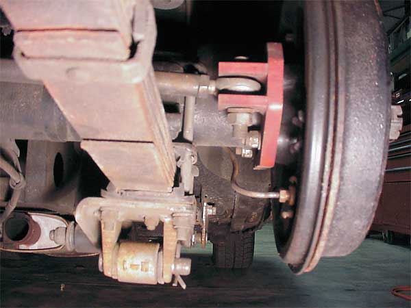
� 1) To make the rod as long as possible. The rod end attached to the rear end will actually � travel in an arc, in relation to the body anchored rod end, as the body moves vertically � on the suspension. This in turn will allow or induce a small amount of lateral movement � between the rear end and the body. The longer the rod, the larger the arc and the smaller � the induced lateral movement. Most of the Panhard rod kits I looked at attached the rod to � the rear end with a clamp or bracket inboard of the spring mounting pad. I found that by � fabricating a bracket which bolted to the back of the axle flange, and immediately behind � the brake backing plate, a much longer rod could be utilized.�
��
�
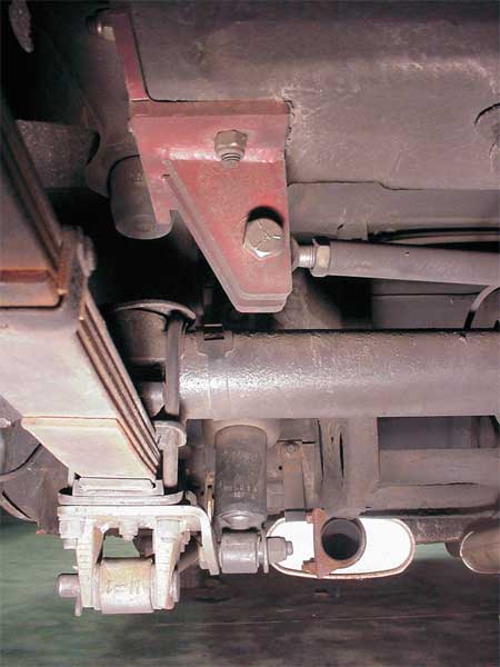
� The body mounted bracket bolts to the bottom and side of the trunk floor, just above the � spring bracket on the rear end. This is the outermost practical mounting point to the body � and results in the longest Panhard rod possible. The mounting bracket dimensions and � construction were described in detail in Vol.V Issue 2 of the Newsletter as are the traction � bar mounts discussed below.�
� 2) The Panhard rod should be level horizontally and parallel with the rear end when the car � is loaded with fuel and a driver. Remember to include these loads when making measurements � for the Panhard rod construction.� �
�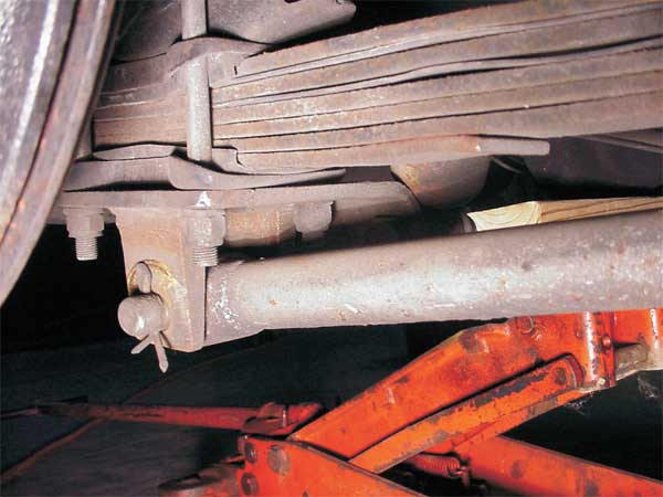
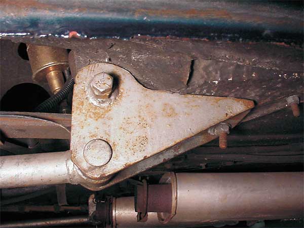
� To prevent axle wind-up in an effective, yet economical manner, conventional traction bars � and their brackets were measured up and fabricated. The forward bracket utilizes the front � spring mount with additional bolting to the car's floor ahead of the spring mount. The rear � bracket was built from 1/4" steel plate sections welded to the stock MGB shock mounting plate. � The traction bars themselves were NOS Cal-Custom swap meet finds, items originally for an � early Mustang. I merely had to shorten them to fit. Some degree of traction bar tuning can � be made by varying the material in the bushings. A softer rubber will provide some give � during a hard launch and soften the shock of the hook-up when the tires get traction.�
�
� Urethane bushings are harder and do not transfer as much motion, giving a faster transfer � of restraint on the rotating rear end and a quicker launch. The racer boys sometimes use � solid metal bushings to minimize axle wrap up; however this is very tough on the traction � bar hardware as well as the rear end itself. �
� To keep the ride supple enough to prevent the tires from losing contact with road on bumpy roads, � I rebuilt the stock '74 rear springs and they have worked very well over the last several years. � A slightly stiffer ride can be obtained by using MGB/GT springs. �
�
�
�
� 1) To make the rod as long as possible. The rod end attached to the rear end will actually � travel in an arc, in relation to the body anchored rod end, as the body moves vertically � on the suspension. This in turn will allow or induce a small amount of lateral movement � between the rear end and the body. The longer the rod, the larger the arc and the smaller � the induced lateral movement. Most of the Panhard rod kits I looked at attached the rod to � the rear end with a clamp or bracket inboard of the spring mounting pad. I found that by � fabricating a bracket which bolted to the back of the axle flange, and immediately behind � the brake backing plate, a much longer rod could be utilized.�
�
| �
Enjoying this article? Our magazine is funded through the generous support of readers like you! � To contribute to our operating budget, please click here and follow the instructions. � (Suggested contribution is twenty bucks per year. Feel free to give more!)� |
� The body mounted bracket bolts to the bottom and side of the trunk floor, just above the � spring bracket on the rear end. This is the outermost practical mounting point to the body � and results in the longest Panhard rod possible. The mounting bracket dimensions and � construction were described in detail in Vol.V Issue 2 of the Newsletter as are the traction � bar mounts discussed below.�
� 2) The Panhard rod should be level horizontally and parallel with the rear end when the car � is loaded with fuel and a driver. Remember to include these loads when making measurements � for the Panhard rod construction.� �
�
� To prevent axle wind-up in an effective, yet economical manner, conventional traction bars � and their brackets were measured up and fabricated. The forward bracket utilizes the front � spring mount with additional bolting to the car's floor ahead of the spring mount. The rear � bracket was built from 1/4" steel plate sections welded to the stock MGB shock mounting plate. � The traction bars themselves were NOS Cal-Custom swap meet finds, items originally for an � early Mustang. I merely had to shorten them to fit. Some degree of traction bar tuning can � be made by varying the material in the bushings. A softer rubber will provide some give � during a hard launch and soften the shock of the hook-up when the tires get traction.�
�
� Urethane bushings are harder and do not transfer as much motion, giving a faster transfer � of restraint on the rotating rear end and a quicker launch. The racer boys sometimes use � solid metal bushings to minimize axle wrap up; however this is very tough on the traction � bar hardware as well as the rear end itself. �
� To keep the ride supple enough to prevent the tires from losing contact with road on bumpy roads, � I rebuilt the stock '74 rear springs and they have worked very well over the last several years. � A slightly stiffer ride can be obtained by using MGB/GT springs. �
�
�
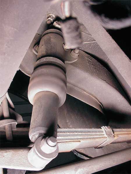
For shock absorbers I used a set of Delco air shocks originally intended for a Corvette. �
These shocks give me a degree of tuning ability and also are very convenient when the "B" �
is heavily loaded for a road trip. I can raise or lower the body about 2-1/4". The bottom �
of the shock installed quite nicely on a bolt run through the stock lower MG shock mount. �
The top of the shocks were secured to the body using a set of old Moss Motoring tube shock �
conversion mounts. However, the top mounting plates are very simple and could be easily �
fabricated. Unfortunately, the shocks I used have been discontinued. A measurement and �
some time at the parts store catalogs should locate something useable. The air fitting to �
pressurize the air shocks in mounted inside the trunk.�
�
� I initially installed 195 series tires on Datsun 240Z wheels and these fit nicely. However, � they did not afford as much traction as I wanted and 215 series tires seemed as if they � would fit. Mounted on Prime aftermarket wheels, they did squeeze under the fenders, but � with insufficient clearance for hard corners. The Panhard rod minimized the lateral movement � of the wheels; however the tire sidewalls actually deflected enough that I did get some tire � rub on the lip of the fenders. I tried to fold the lips up and back to get them out of the � way, but the double ply of sheet metal was way too stiff and I started to actually bend the � fender out of shape. The recourse was to cut the lip away in about the center of the spot � welds which hold the two plies together. I used a 3" abrasive disc on an air grinder. It � took a steady hand and some patience, but a smooth cut was finally made on both sides, � giving about 3/8" additional clearance per side. The raw cut edges were dressed with a � power sander, painted and sealed. I have had no more tire rub even when doing a 360 spin on � the race track. (Though that was the least of my worries at that particular moment!)�
� As the traction bars, Panhard rod system and shock mountings were either fabricated or swap � meet buys, the cost of the rear end suspension was minimal, probably under $50.00. Add $35.00 � for the shocks (a purchase at the Hershey swap meet) and the whole set up came in at under � $100.00 and this over a period of a year, thus keeping it under the radar screen of "upper � management" who kept a close eye on any fraud or shortages in the family.�
� Disclaimer: This page was researched and written by Kurt Schley. Views expressed are those of the author, � and are provided without warrantee or guarantee. Apply at your own risk.�
�
�
�
� I initially installed 195 series tires on Datsun 240Z wheels and these fit nicely. However, � they did not afford as much traction as I wanted and 215 series tires seemed as if they � would fit. Mounted on Prime aftermarket wheels, they did squeeze under the fenders, but � with insufficient clearance for hard corners. The Panhard rod minimized the lateral movement � of the wheels; however the tire sidewalls actually deflected enough that I did get some tire � rub on the lip of the fenders. I tried to fold the lips up and back to get them out of the � way, but the double ply of sheet metal was way too stiff and I started to actually bend the � fender out of shape. The recourse was to cut the lip away in about the center of the spot � welds which hold the two plies together. I used a 3" abrasive disc on an air grinder. It � took a steady hand and some patience, but a smooth cut was finally made on both sides, � giving about 3/8" additional clearance per side. The raw cut edges were dressed with a � power sander, painted and sealed. I have had no more tire rub even when doing a 360 spin on � the race track. (Though that was the least of my worries at that particular moment!)�
� As the traction bars, Panhard rod system and shock mountings were either fabricated or swap � meet buys, the cost of the rear end suspension was minimal, probably under $50.00. Add $35.00 � for the shocks (a purchase at the Hershey swap meet) and the whole set up came in at under � $100.00 and this over a period of a year, thus keeping it under the radar screen of "upper � management" who kept a close eye on any fraud or shortages in the family.�
� Disclaimer: This page was researched and written by Kurt Schley. Views expressed are those of the author, � and are provided without warrantee or guarantee. Apply at your own risk.�