
 | �
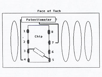 | �
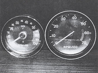
| Photo 1: 73-76 RVC1410 and 1980 RVC2432 | Figure 1: Chip terminal numbering. |
| (Note: there's a significant error in Figure 1. Scroll to the bottom of the article for detailed explanation.) | |
Converting the MGB Tachometer to V-8 Calibration
� By: Kurt Schley �� (This article appeared in Volume VIII Issue 1, January 2000.)�
�
Background
��
On many MG V-8 conversions, the last item to be addressed is often the �
modification of the tachometer (and usually speedometer too!) to V-8 mode. �
How to build the engine, get it into the MG, uprate the suspension and most �
other phases of a V-8 conversion are well documented and straightforward. �
However, what goes on in the little round case behind the face of the stock �
MGB rev counter and how a DIY conversionist can change it to a V-8 version �
has generally been a mystery. Some instrument repair companies can convert �
a tach quickly and for a fairly reasonable fee while others will shy away �
from such modifications or charge an arm and a leg, citing the "extensive �
work" needed to make the conversion. �
�
Various reasons are often cited for not having a converted tach. For the real �
hard core DIY types, it is sometimes difficult to concede that there are some �
occasions when one must farm out work to a professional and pay the price. �
Then there is the fact that having the tach converted is not an absolute �
necessity in order to drive and enjoy the car. The unmodified "B" tach, when �
wired to the V-8, will merely read 2x the actual engine revs and it is easy �
to become accustomed to subconsciously dividing the tach reading while driving. �
Then there is the cheap thrill of watching the needle on a 4-cylinder tach �
bounce back and forth wildly when the V-8 winds over 3500rpm, invoking fantasies �
of high-revving F1 driving as you thunder around the on-ramp! �
�
At the 1998 MG V-8 meet in Annapolis MD, Carl Floyd shared the information �
that he had run across a website which contained instructions for converting �
a "B" tach for V-8. The site was that of Leon Zak, who had built an MGB V-8 �
and had also devoted quite a bit of time in detailing the conversion on the �
site, including some directions and photos of the tach changeover. Based on �
the information furnished on Leon's site, Cleveland area V-8'ers, Jeff Foote �
and Bernie Posey decided recently to give the process a try and found it to �
be rather simple, aside from requiring some soldering skills and a steady hand. �
Bernie recently changed over three tachs in a matter of 15 minutes while the �
process was photographed and recorded.�
�
 �
�
The Tachometers
�� During the 18 years of MGB production, there were six tachometer models � used in the cars. The tach model is printed in white letters along the � bottom edge of the tach face. The earlier tachometers were about 3-1/8" � (80mm) in diameter, which grew to 4" (100mm) with the 1977 rubber bumper � cars. (Photo 1) The 1973-80 tachometers are suitable for conversion to � V-8 by "the Zak method".�
�| Year(s) | Model | Suitability / Comments |
| 1962-67 | RN2312-01 | This model used a mechanical, cable driven tachometer and would require a small gear reduction box to be fabricated. This can be furnished by any competent speedometer shop. |
| 1962-67 | RV12401-00 | Electric with positive ground. |
| 1968-71 | RVI 1433/00 | The internal circuitry on this model does not lend itself to "the Zak method" conversion. |
| 1972 | RVI 1439/00 | For this year only, the tach already has a potentiometer in the circuit. � (John Twist at University Motors advises that this built-in pot can � adjust the rpm range quite a bit. It is possible that there is enough � adjustment in the pot that it can he calibrated for V-8 use without � modifications. I did not have access to a '72 car to attempt the � adjustment, so any readers who have a '72 MGB and give it a try, please � let me know the results. -Kurt) |
| 1973 | RVC 1410/00R | This was the last series of the 3-1/8" face tachometers. The internal circuitry is very similar to that of the later models. |
| 1977-79 | RVC2432/00 | First of the 4" diameter tachs |
| 1980 | RVC2432/01 | Sometimes referred to as "the Spitfire tach" as the face is very similar to that of the Triumph. |
�
 | �
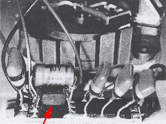 | �
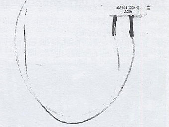
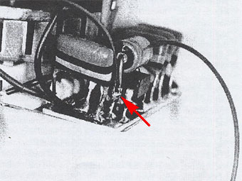
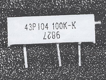
| Photo 2: Potentiometer with leads soldered on. | Photo 3: Tach circuitry showing location of chip (arrow) |
�
| �
Enjoying this article? Our magazine is funded through the generous support of readers like you! � To contribute to our operating budget, please click here and follow the instructions. � (Suggested contribution is twenty bucks per year. Feel free to give more!)� |
�
 | �
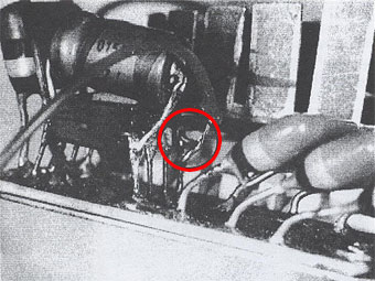 | �
| Photo 4: Lead soldered to chip #4 terminal. (arrow) | Photo 5: Lead soldered to chip #7 terminal (circle) |
The Technique
�� "The Zak Method" tachometer conversion method is to wire a potentiometer � (see sidebar) across the only chip in the instrument. Turning the screw on � the potentiometer adjusts the number of impulses (picked up from the ignition � system) which the tach recognizes. Once the "pot" is installed, the tachometer � then has to be calibrated so that it is indicating the correct rpm.�
�| Step | Technique |
| 1. | Set a multimeter to 100 ohms. |
| 2. | Attach one lead of the multimeter to the center lead on the pot. |
| 3. | Attach the second multimeter lead to either of the side leads on the pot. |
| 4. | Run the screw on the pot in and out, checking to see that the multimeter reading changes, thus ensuring that the pot is good. |
| 5. | Adjust the pot to around 100k ohms. |
| 6. | Cut off, or bend over and tape, the third pot lead. (It will not be used.) |
| 7. | Cut two 3" lengths of 22 or 24 ga. stranded wire. |
| 8. | Strip approximately 3/8" of insulation from either end of the wires. |
| 9. | Solder a wire to each of the remaining pot leads. |
| 10. | Insulate the soldered connection with heat shrink tubing. (See photo 2.) |
| 11. | Remove the glass from the tachometer by grasping the chrome trim ring firmly and twisting the case. The ring should rotate in the case about 3/8" and disengage from the case. |
| 12. | Remove the screws in the back of the case which hold the tach face and circuitry in place. |
| 13. | Locate the only chip in the circuit hoard. (Photo 3 and Figure A.) |
| 14. | Carefully bend the three red/yellow/black striped diodes away from the chip to gain access to the chip's number 7 terminal. (Photo 3.) |
| 15. | Solder one of the pot wires to the chip number 4 terminals. (This is one of the terminals to which a cylindrical blue capacitor is also attached.) (Photo 4.) |
| Note: | � Bernie's soldering method is to bend the free end of the pot wire � into a small "U' shape. The wire end is then dabbed with soldering flux � and looped around the chip terminal. The tip of a pencil type soldering � iron is loaded with a tiny bead of molten solder and the bead touched to � the wire/terminal joint. Unless you are sure of your soldering skills, it � is better to practice this a few times with scrap wire! |
| 16. | Solder the second pot wire to the chip's number 7 terminal. (Photo 5.) |
| 17. | Attach the tach (with case not installed) to the MG's tach wires, temporarily securing it so that the circuitry and face are protected and the pot is accessible. |
| 18. | Attach a high quality dwell tach to the engine and position it where it can be easily seen from tile cockpit. |
| 19. | Start the car and check that the dwell tach and dashboard tach are both responding. |
| 20. | Adjust the tach reading with the screw on the pot at 1000, 3000 and 5000 rpm. |
| Note: | �
A) As detailed on Leon Zak's website, the calibration of the modified tachometer can also be set with an oscilloscope. B) If you do not have access to an accurate dwell tach, the modified tachometer can be set by any automotive instrument shop for a nominal fee. |
| 22. | Remove the tach from the car. |
| 23. | Place a wrap of electrical tape around the pot and tuck the pot into the case, taking care that the pot or wires do not snag on any of the circuitry. |
| 24. | Install the screws holding the circuitry to the back of the case and install the glass and trim ring. |
| 25. | Reinstall the tach into the dashboard. |
�
�
�
The Potentiometer
��
A potentiometer, or "pot'' is basically a resistance adjuster. As the screw �
on the put is adjusted in or out, the pot varies the resistance to the voltage �
being run through it. By regulating the voltage read by the tach circuitry, �
the tach reading can be calibrated to indicate the V-8's engine speed or rpms. �
�
The potentiometer used in this article as a 100K 15-turn 3/4 Watt unit made �
by Jim-Pak Electronic Component. Leon Zaks used a 10-turn 100K pot. The number �
of turns (i.e. how many times the adjustment screw turns through its entire �
range) is not critical, but the pot should have a I100K capacity. �
�
Potentiometers such as these can he sourced from industrial or large hobbyist �
electronics companies. (Radio Shack, at least in the Cleveland area, doesn't �
carry them.)�
�
Special thanks to Bernie Posey and Jeff Foote for their advice and cooperation �
in composing this article - especially Bernie, who had to endure trying to solder �
with my camera flash going off in his eyes every few seconds! -Kurt �
�
�
The following correction appeared in MG V-8 Newsletter Volume VIII Issue 2, May 2000:�
�
In the article "Converting the MGB Tachometer to V-8 Calibration", which appeared in the last �
Newsletter (Volume VIII, Issue 2), there was a major error. In the wiring schematic illustrated �
in Figure 1, the potentiometer is shown as being connected to chip terminals 4 and 7. In �
actuality, the potentiometer should have been shown as being attached to terminals 3 and 8.�
The article text must be correspondingly corrected. The attachment points shown in the photos �
are correct.�
�
I apologize for the error! Hopefully all subscribers received a postcard a couple months ago �
advising of the correction. I would like to thank reader Ben Pope who e-mailed me shortly �
after the was mailed and advised me to the error. -Kurt�
� Disclaimer: This page was researched and written by Kurt Schley. Views expressed � are those of the author, and are provided without warrantee or guarantee. Apply at your own risk.�