 �
�
�
�
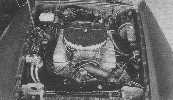
Dave Nelson's Buick 215 Powered 1977 MGB
�
MGB-V8
� This article appeared in The MG V-8 Newsletter - Issue VI, Volume 1 - Spring 1998�� by: Dave Nelson�
�
It's the sound I like best. The sound of a balanced eight cylinder idling at 600 rpm without a miss.�
The rrRRipp of instant throttle response with the slightest pressure on the gas pedal. The muscle car�
AAAHHHRRRR!!! when you accelerated at full throttle from a stop. You guys that have driven one know�
exactly what I'm talking about. A teenage girl pointed and said "Dad, look at that nice little green�
MG. Do you think I could get one like that? Pleeease Dad?" I pop the clutch and floor it. The rich�
blast of V-8 exhaust rips the air. The MG disappears in a cloud of burning rubber. Black particles�
from my rear tires pelt the windshield of Dad's car. I shift to second and smoke the tires again,�
then disappear around the next bend in the road. Dad hits the windshield washer knob... "I don't think�
so honey."�
�
The car is a sleeper. A '77 MGB. BRG paint and the standard MGB vinyl stripe down by the rocker panels.�
No V-8 logo or custom license plate. The only clues are the pair of tail pipes where the single used�
to be; and the sound!�

Engine
�- �
- '61 Buick Special 215 CID bored 0.040"over �
- Deck height milled for 9.2:1 �
- Dished pistons �
- Stock Buick 4bbl manifold �
- Carter 500 SFB �
- Edelbrock 1207 air cleaner �
- GM 55 amp alternator (from '80 Chevy 350) �
- Balanced �
- Short nose water pump �
- Lumenition ignition �
- Stock MGB coil �
- MGB radiator - turned around, larger necks, filler plug on top. �
- MGB cooling fans (2) and 17" fan on water pump �
- High volume oil pump, galleries drilled to 1/2" �
- Remote oil filter �
- Lightened Buick flywheel �
- TR-8 clutch �
- Modified clutch fork �
- SD1 5-speed �
- Glen Towery drive shaft with TR-8 u-joints �
- Rover-Buick pilot bearing adapter
Suspension
�- �
- Moss tube shocks �
- ADCO short front springs �
- 1/4" lowering kit (rear) �
- cast aluminum rims from '81 Dodge Charger �
- 14" Goodyear tires
�
I'm no expert but I learned a lot stuffing this engine in my MG. I'm writing this in the hope that�
somethine I thought was clever can be used by someone else. I found the engine in a California�
junkyard. It was complete from fan to flywheel, carb to oil pan, but had been sitting there for�
years. It was caked with grease and dirt. I also bought a blown Buick engine for some spare parts�
for another $50. I got my engine rebuild kit from Kanter. They gave poor service. I don't recommend�
them.�
�
The first time I put the short block together I noticed there was a lot of space between�
the deck and the piston tops at TDC. I measured the combustion chamber volume using plastic from�
a CD holder, Vaseline, and a syringe. The compression was only 7.5:1. So I took the short block�
apart and had it milled. Well, the machinist over-did it, and when I got the short block back�
toghether, one of the pistons stuck out of the block about 0.006". The rest of the pistons had "0"�
deck height. I took the tall piston out and sanded it on a glass plate covered with fine emery cloth�
until it had "0" deck height. I was using a 0.020" thick shim head gasket, so there was plenty of�
clearance between the pistons and the heads, even with "0" deck height. The compression ratio is now�
9.2:1, and the engine works well on regular gas. With the deck height milled (about 0.040") the�
intake manifold bolts were just a tad tricky to get in the heads because the manifold sat higher�
and the bolts rubbed against it as they were tightened. If I had to do it again I would have�
slotted the bolt holes in the manifold a little to make the bolts turn more easily into the heads.�
�
I used stock rope seals, front and rear. Not elegant, but no problem. Had the machine shop drill�
the main oil gallery out to 1/2" with a long drill bit you can get at Sears. Used an oil pick-up�
with a half inch diameter tube.�
�
Gooping
�� Proper gooping is certainly one secret to success. There are lots of different goops that help hold� this engine together. Here's a list of the goops I used:�
�- �
- Used anti-seize on every steel bolt that went into aluminum. �
- Gooped both sides of the intake manifold gasket (valley cover) with silicone to prevent vacuum leaks. �
- Gooped the front and back of the valley cover and the oil pan and valve cover gaskets with silicone to prevent oil leaks. �
- Gooped the water pump and thermostat cover with silicone to prevent anti-freeze leaks. �
- Gooped the oil lines to the remote oil filter and the fitting from the top of the filter holder to the oil pressure gage tube fitting with Locktite to prevent oil leaks. �
- Gooped the fittings leading to the clutch cylinder with Locktite to prevent brake fluid leaks. �
�
NOTE: a NAPA guy told me about this stuff called "PST". It is a special goop for sealing threads.�
If I had it to do again I'd use this stuff in place of the Locktite for the oil and brake fluid lines.�
�
Advice
�- �
- Use anti-seize on all steel bolts that go into aluminum! �
- Prevent leaks! Vacuum, oil, antifreeze, brake fluid, etc., etc.
�
�
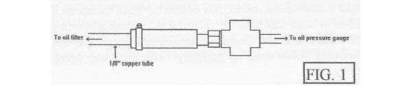
Figure 1: Oil pressure gauge connection.
�
Oil Filter
��
I mounted the remote oil filter on the right fenderwell, leaving enough slack in the oil tubes to allow�
the engine to move a little. I used a 1/8" copper tube from the oil filter holder top to the standard�
MGB oil pressure gage fitting on the firewall. At the firewall end, I cut off one end of the�
rubber-braided-looking MG oil pressure tube and shoved the 1/8" copper tube inside several inches and�
tightened a hose clamp around it. Works great and looks good. See Figure 1. When I drilled and�
tapped the oil filter holder for the oil pressure gage tube, I made a mistake. I ran the tap too deep,�
so the small pipe fitting I used never tightened up in the threads. Luckily, the Locktite I used made�
a good seal, but if I had it to do over again I would not run the tap all the way through the�
hole I drilled.
�
| �
Enjoying this article? Our magazine is funded through the generous support of readers like you! � To contribute to our operating budget, please click here and follow the instructions. � (Suggested contribution is twenty bucks per year. Feel free to give more!)� |
�
Installation
��
From pulling into the shop with MG 4cyl power, to pulling out of the shop with the Buick engine in place�
took 12 work hours. Of course the Buick engine was only resting on its mounts with nothing hooked-up,�
and not yet connected to the rear cross member. My pretty wife towed me home. If I did it again�
I'd take more time in the actual installation and do the required pounding "just right", prime and�
under coat the tunnel better, clean all the gunk out of the frame rails, maybe paint the engine compartment,�
etc.
�
The Pounding
��
There are four places in the engine compartment that need pounding. The transmission tunnel, the fender�
wells for the headers (2 places) and the left fender well for the alternator (Buick only, not Rover.)�
The tunnel pounding took about an hour. Each of the the other three places took less than 10 minutes each.�
�
The tunnel: there is a square reinforcement that runs across the top of the tunnel at the engine end.�
This needs to be pounded up until it's flat. That's the hard part. The rest of the tunnel is relatively�
soft. It needs to be pounded until a straight edge lays flat from the shifter hole to the newly-flattened�
square reinforcement. Look at the Rover transmission. You'll see a raised chunk of iron on it a few inches�
behind the bellhousing. Make sure you give the tunnel a few extra whacks to clear that. If you don't�
pound enough, the transmission will hit the tunnel when you bolt up the rear crossmember. There are two�
ways to fix that problem: (1) take the engine out and pound some more, and (2) use washers between the�
crossmember and the frame. The washer idea is tacky, so make sure you pound enough.�
�
�
�
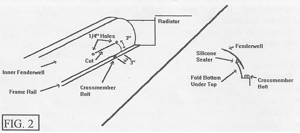
Figure 2: Method for avoiding wrinkles in fenderwells.
�
For Better Pounding
��
For the headers: drill a 1/4" hole 3" forward of the frame nut on the left and right frame rails in the�
engine compartment, and three inches above the frame. Then on a line parallel to the frame rails and�
one foot behind the first hole, drill a second hole. Using a handheld electric jig saw with a metal�
cutting blade, saw a straight cut between the two holes. This is the area to pound for the headers.�
As you pound, let the sheetmetal below your cut slip outside the metal above your cut. See Figure 2.�
This will prevent making ugly wrinkles in the engine compartment from the pounding. I didn't do this, and�
I have random dents in the fender wells where I pounded. If I did it again I would make the cuts�
for proper pounding.�
�
Any pounding you do will knock the undercoating and maybe primer off the other side of the metal.�
You'll want a can of primer and one of undercoating handy after pounding to touch things up on the outside�
(wheel side) of the fender wells. If you make the cuts for neat pounding, you'll need to seal them with�
silicone on the wheel side of the fender well to keep water out.�
�
�
�
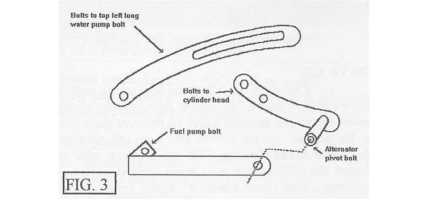
Figure 3: Alternator mounting bracketry.
�
Alternator Bracket
��
The alternator bracket was a beautiful piece of work from D&D Fabrication. The mounting arm bolted�
to existing holes in the left head, and had a lug positioned for the mounting/pivot bolt that dangled�
the alternator just to the left of the left valve cover. A second steel strap held the front of the�
alternator pivot bolt and connected to the fuel pump bolt on the engine. The adjustment strap bolted�
to the top long bolt in the waterpump on the left side. (I had to bend that strap into about a half inch�
wide Z shape to get it to line up exactly with the alternator adjustment ear.) See Figure 3.�
The alternator pulley lined up perfectly with the water pump and crank pulleys.�
�
�

�
Figure 4: Oblong-to-round radiator ports.
�
Radiator
��
Turn the radiator around, left for right. Take off the existing necks and seal the holes. Leave the hole for�
the thermostatic fan switch as is. Put the top neck and overflow tube on the new left side and bottom neck�
on the new right side. Glen Towery got me some nice necks that had oblong connections to the radiator and�
works great. See Figure 4. The Rover thermostat cover is different than the Buick one. Use the�
Rover unit for the MG standard radiator mod.�
�
�
�
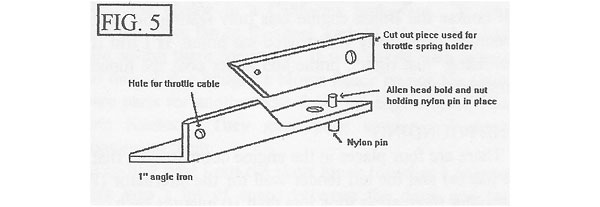
Figure 5: Simple throttle cable bracket.
�
Throttle Cable Bracket
��
I made what I thought was a nice throttle cable bracket out of a 4" piece of angle iron. Here's how.�
The Carter carb flange has a total of eight mounting holes, two at each corner. Only four are used to�
mount the carb. I used the back left carb stud to also hold my cable bracket. To prevent the bracket�
from rotating, I fastened a pin to the bracket that fits into the second, (unused) flange hole in the�
back left corner of the carb. I trimmed off the angle to make it easier to tighten the mounting nut�
and used this trimmed off piece as my throttle spring holder after drilling it for the front left intake�
manifold bolt and drilling a smaller hole in the other end to hold the throttle spring. See Figure 5.�
�
�
�
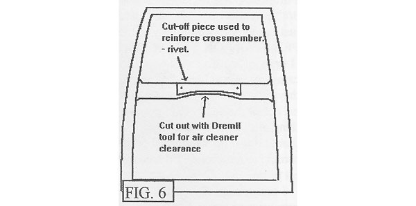
Figure 6: Air cleaner and hood clearance.
�
Air Cleaner and Hood Clearance
��
I used an Edelbrock 1207 low profile air cleaner, but replaced the element with one that is only about�
2" high instead of 3". This filter looks tall, it's tall in the middle. It turns out the clearance problem�
was only in the front. To find out how close the air cleaner would come to the hood, I put a thin layor�
of my daughter's playdough on the air cleaner and slowly pushed the hood down until it touched. The mark�
on the playdough showed the hood only touched about half of the hood's crossmember. I used a Dremel Tool�
with a cutoff wheel to cut an arc out of the crossmember where the playdough had touched. Then, I took�
the piece that I had cut out, trimmed it a little, and riveted it to the remaining portion of the hood�
crossmember to strengthen it. See Figure 6.�
�
To use the Edelbrock filter you need a banjo bolt ninty degree fitting for the carb. A manual choke would�
clear this air cleaner, but my carb has an electric choke, and the choke interefered with the air cleaner�
and prevented it from making a good seal with the carb. I took the Dremel Tool with a sanding drum to the�
choke and the air cleaner to get the required clearance. Not ideal, but it worked.�
�
�
�
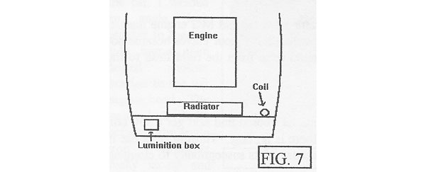
Figure 7: Locating the Lumenition control box.
�
Wires
��
There was an unused, greenish wire in the MG harness that ran with the temperature sender wire. I think�
it was for a service interval counter (which my car never had). It was hot with the key on, so I used�
it for the electric choke. My four cylinder MG engine had a Lumenition ignition. I loved it. No points�
to replace. Never had to adjust the dwell. Glen put some parts in my Buick distributor that made it�
compatible with the Lumenition. This was much cheaper than buying a new distributor. I mounted the�
Lumenition box on the front right apron under the hood, in front of and to the right of the radiator.�
See Figure 7.�
�
Used 3/8" PVC wire conduits to run Lumenition, coil, alternator, fan switch, and temp sender wires.�
Really reduced the clutter. Looks great. Those nylon zip ties are very cool too. NAPA had the right�
plastic connector to hook into the new alternator. This made the wiring look more professional.�
�
Dip Stick
��
I put in a Ford dipstick and dip stick tube. Do this before you build up the short block, since it�
requires drilling out the dip stick hole in the block. I left the tube too long so I could adjust�
it to the right length once the engine was filled with oil and ran a little. I used a tubing cutter�
for the final tube length adjustment, matching the full mark on the dipstick with 5 quarts of oil.�
Stuffed a rag down the tube while cutting it to avoid shavings in the oil.�
�
Plug Wrench Mod
��
When I had the heads done, two of the spark plug holes had to have Helicoils put in because of bad�
threads. The Helicoils were put in just a little off-axis (maybe one degree off) and the way the�
plugs sit down in a deep well I couldn't get a regular spark plug socket on the plugs to tighten them.�
It worked good to grind down the first 1" of a spark plug socket to a thinner wall thickness. This�
allowed the wrench more clearance, within the spark plug well, to turn.�
�
�
�
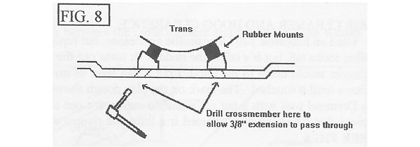
Figure 8: Modifying the transmission crossmember.
�
Transmission and Crossmember
��
Three things caught me on the transmission. I'll discuss two here: (1) I didn't confirm the operation�
of the reverse light switch before I installed the transmission. It works, but I have to push the�
shifter to the left and hold it to make it work. I'm sure a simple adjustment out of the car would�
have prevented this. (2) There's a nylon clip that holds the clutch push rod to the clutch fork. I�
didn't install this before putting the engine in the car and it was a hassle to get the clutch�
cylinder installed in the bellhousing. So remember to install the clutch pushrod before installing�
the clutch fork.�
�
Modifying the transmission crossmember was easier than I thought it would be.�
�
- �
- With the engine in the car, put the shock mounts on the transmission. �
- Position the crossmember exactly where you want it, relative to the shock mounts. �
- Adjust the crossmember slightly forward or aft to line up the front holes on the ends of the� crossmember with existing threaded holes in the MG frame. (Use long bolts to hold the� crossmember in this position.) �
- Mark the crossmember where the shock mounts touch it. �
- Use a handheld jigsaw with a metal cutting blade to cut slots at the marks. �
- Install the crossmember with bolts through the front crossmember mounting the holes into� the threaded holes in the frame. (The slots you just cut will slide onto the shock� mount studs.) �
- Drill holes through the aft crossmember mounting holes into the MG frame to accept one�
inch long lag bolts.
�
To make it easier to tighten the shock mount nuts, I drilled two holes in the crossmember big�
enough to allow a 3/8" extension through, and lined up with the nuts. Now I just�
put the extension through the hole, reach around and put the 9/16" socket on it, and push it�
on to the nut. See Figure 8.�
�
Pre-Start Oil Pressure
��
I epoxied a 12mm socket onto the shaft of an old distributor, and took the drive gear off the shaft�
so it wouldn't engage the cam gear. Then I installed the distributor in the engine, being sure the�
distributor shaft engaged the oil pump. Then I put a 3/8" drive adapter into my electric drill and�
hooked that to the 12mm socket. Spinning the drill turned the oil pump. I got about 25 psi out of the�
set-up. (I had my wife watch the gage in the cockpit.) A couple of things surprised me: (1) My drill�
is just a little 1/4" thing with a low horsepower motor. I was pleasantly surprised that it did such�
a good job turning the oil pump. (2) Even though I had packed the pump with Vaseline, it took 10 to�
15 seconds to generate any oil pressure at all, even with the drill turning at full speed.�
I'd hate to think of my brand new engine running that long with zero oil pressure. I'm�
glad I spun up the oil pump.�
�
I put the real distributor back in, which is no small trick since the meshing drive gears spin the�
distributor shaft about a 1/8th turn prior to the distributor shaft engaging the oil pump. Hooked up�
the battery, sprayed a little starting fluid down the carb, and cranked. After about two seconds of�
cranking it fired up. Smoke, noise, spinning machinery... it was great. Ran it for a couple of minutes�
until the temp gage showed warm (no belt, remember?) and shut it down.�
�
The second time I started the engine, the starter wouldn't turn over, and I noticed a spark from the�
old MG engine manual choke cable to the engine where it touched. The day before I had read a tip in�
the Moss catalog that if your cables become hot you should check your engine's grounding. The light�
in my head went on and I put a ground strap from the right head to the MG frame. That fixed the problem.�
�
Carb Size
��
I was worried about the Carter 500 being too much carb for this engine. All the Ve equations I could�
find said get a 350cfm carb for this size engine. But since the secondaries are vacuum operated on the�
Carter, there is no bog. Throttle response is instant. Much better than the MG engine.�
I had been discouraged from getting a Holley because of its susceptibility to clogging from dirt. I�
can't speak for that, but I know the Carter carb works great.�
�
�
�
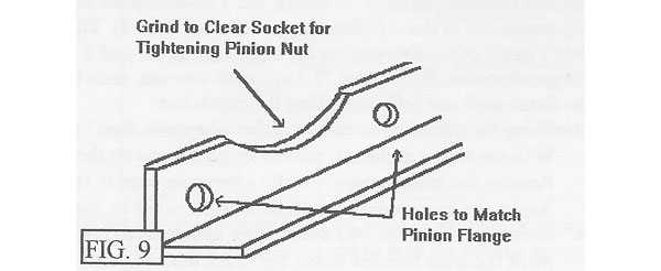
Figure 9: A shop-built driveshaft tool.
�
Miscellaneous
�- �
- I put the coolant overflow tank on the left fender well, right next to the left cylinder head,� behind the alternator. Drilled two holes. Piece of cake. �
- A standard pipt thread adapter allowed the use of the MG temperature sender in the Buick manifold. �
- I used a regular pipe fitting adapter to connect the MG anti-backfire valve onto the back vacuum� outlet on the Carter carb. Used the stock vacuum hose. Works great. �
- I put the coil on the aft side of the left radiator wing support. This position allows use of a� stock set of Buick plug wires. �
- Used baling wire wrapped around the three pulleys to estimate the belt length. The baling wire� was 106cm long. Then I bought five belts of different sizes starting with 109cm. The belt that� fit was 114.5cm. I returned the other four belts. �
- Balance your drive shaft. Mine came back from the balancer with a big weight on it. I'm� glad I did it. It would have wobbled badly. �
- I had to replace the pinion flange to match the bigger one on my drive shaft. Made a tool out of� 1" angle iron to hold the flange for tightening. This was indispensable. See Figure 9. �
- At the Edwards AFB library I found an old Chiltons manual and a Motor manualk that had data for the�
1961 Buick engine I used. The books were life savers. They had torque values, firing order,�
head bolt tightening sequence, etc. Very valuable.
�
� Note: Dave Nelson's MGB-V8 was purchased by James Therry in 2010. �
��
� Disclaimer: This page was researched and written by Dave Nelson. Views expressed � are those of the author, and are provided without warrantee or guarantee. Apply at your � own risk.�
�