�
 �
�
�
�
�
�
�
�
�
�
 �
�
� by: James Jewell and Andrian Akhurst�
� Ok, so your MGB doesn't really have abdominal muscles, but this article will show you � how to beef up your roadster's mid-section, which many have argued is a weak point when � converting to a high-torque engine.�
� The MGB is one of the earliest production unibody, or monocoque automobiles in the world. � Legend holds that Abingdon went to great lengths to over-design the car to ensure its � strength and rigidity in the face of insufficient unibody design data. Keep in mind that � the computer was not available as a design tool to auto houses in 1960, and that there � wasn't a large body of data available on this new technique (outside of the aerospace � industry). So the resulting design was quite stiff, even by today's standards.�
�
�
�
�
MGB Chassis Reinforcement: "How to Give your MGB 6-pack Abs"
� This article appeared in The British V8 Newsletter - Volume XII, Issue 3 - September 2004�� by: James Jewell and Andrian Akhurst�
� Ok, so your MGB doesn't really have abdominal muscles, but this article will show you � how to beef up your roadster's mid-section, which many have argued is a weak point when � converting to a high-torque engine.�
� The MGB is one of the earliest production unibody, or monocoque automobiles in the world. � Legend holds that Abingdon went to great lengths to over-design the car to ensure its � strength and rigidity in the face of insufficient unibody design data. Keep in mind that � the computer was not available as a design tool to auto houses in 1960, and that there � wasn't a large body of data available on this new technique (outside of the aerospace � industry). So the resulting design was quite stiff, even by today's standards.�
�
�
Anyone who has ever driven a post-1979 Ford Mustang will have to agree, and I'm not even �
talking about the convertible! To this day, the only definitive design flaw to have shown �
up in the 'B (not including the 400lb, 90Hp 4-cylinder) is the 'Crack of Doom' on the �
door skin of 90+ percent of roadsters. An informal poll I took of MGB drivers who had �
been in accidents shows that the little 'B' protects the driver quite well in all but �
the most serious accidents. Then again, by definition, I couldn't interview people who �
had been killed in an MGB, so my data may be lopsided. Still, of all the people I spoke �
with, only one spoke of a known fatality in a 'B'. If any of you faithful readers has a �
good or bad MGB accident story, or know of any tragic accidents where you believe the �
driver would have been safer in another car than the MGB, please e-mail or write me. I �
may do a future article on that topic, as well as ways of strengthening the 'B'.�
� While the B's structural design appears to have rust as its only mortal enemy in cars � with moderate output, there is a potential Achilles Heel for those who push torque to � the maximum. It is the front leaf-spring perch that transfers all the torque at the rear � wheels into the forward force acting on the car body. All of that force is, in effect, � pushing on the car at the flimsy sheet metal intersection of the floor and the rear � bulkhead. My gut tells me the forces in play are nowhere near the yield strength of � mild steel, but the flimsy nature of the nearly-flat sheet metal in that area of the � car will flex, and flexing ultimately leads to fatigue and cracks, not to mention � alignment problems. If you've ever stood on the bare floor-pan of your MGB during a � restoration, you'll have no doubt noticed the flexing (unless you are standing right � over the central cross-member (jacking point). While I have never personally heard of � any measurable deformations or structural failures in B's with engine conversions, my � inner engineer tells me that routing all acceleration forces through a single layer of � sheet metal and some spot welds is marginal at best, and it appears that the engineers � who spawned the RV8 came to the same conclusion, as we will see momentarily. The way to � avoid this potential problem is to alter the load path so that acceleration forces act � through more rigid portions of the car that will better distribute those forces. In � addition to the stock leaf-spring suspension, this approach is also applicable to any � 3 and 4-link rear suspension upgrades that use that front leaf-spring perch as a � mounting point. �
� �
�
�
�
�
� While the B's structural design appears to have rust as its only mortal enemy in cars � with moderate output, there is a potential Achilles Heel for those who push torque to � the maximum. It is the front leaf-spring perch that transfers all the torque at the rear � wheels into the forward force acting on the car body. All of that force is, in effect, � pushing on the car at the flimsy sheet metal intersection of the floor and the rear � bulkhead. My gut tells me the forces in play are nowhere near the yield strength of � mild steel, but the flimsy nature of the nearly-flat sheet metal in that area of the � car will flex, and flexing ultimately leads to fatigue and cracks, not to mention � alignment problems. If you've ever stood on the bare floor-pan of your MGB during a � restoration, you'll have no doubt noticed the flexing (unless you are standing right � over the central cross-member (jacking point). While I have never personally heard of � any measurable deformations or structural failures in B's with engine conversions, my � inner engineer tells me that routing all acceleration forces through a single layer of � sheet metal and some spot welds is marginal at best, and it appears that the engineers � who spawned the RV8 came to the same conclusion, as we will see momentarily. The way to � avoid this potential problem is to alter the load path so that acceleration forces act � through more rigid portions of the car that will better distribute those forces. In � addition to the stock leaf-spring suspension, this approach is also applicable to any � 3 and 4-link rear suspension upgrades that use that front leaf-spring perch as a � mounting point. �
�
�
�
�
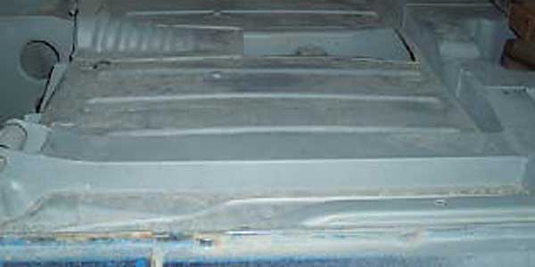
Before we try to solve the problem, let us consider the design of the 'B' and how forces �
travel throughout its body. Even though the MGB is of unitized construction, there are �
portions of the design that resemble traditional frame rails. Starting at the nose of �
the car, there is the front sub-frame which handles loads from the front bumper to the �
middle of the cockpit, including all front suspension loads. At the middle of the car, �
the sub-frame ties into the central cross-member which runs from side to side connecting �
both the left and the right "frame rails" and the all-important rocker panels. As just �
about every non-California MGB has had rusted-out rocker panels at some point in its �
life, we're all familiar with the role they play in keeping the body from bending in �
the middle (one could argue that the transmission tunnel aids in that role). There is �
also a rear sub-frame that ties into the aft end of the rocker panels. But here the �
problems begin. The forward leaf-spring perches don't tie directly into the previously �
mentioned rigid members. There exists a flat, unobstructed, open stretch of sheet metal �
(floor panel) between the spring perch and the central cross-member. The path of least �
resistance would be to run some kind of rigid member straight from the perch to the �
cross-member. As luck would have it, this method works well, and the DIY community can �
either buy parts in the aftermarket, or fabricate something themselves. The load-path �
now starts at the spring-perch, runs along the new member (distributing some stress to �
the floor-pan at every spot-weld along its length) and ties into the central cross-member �
where the remaining load is distributed to the previously mentioned structural pieces.�
��
�
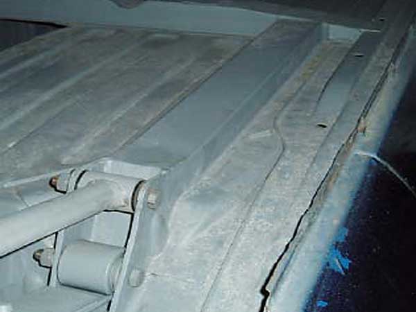
� As I mentioned earlier, the RV8 engineers also felt that this was a potential weak-spot, � and so they designed a load-bearing member that runs the same span. It also allows the � use of anti-tramp bars and handles the extra twisting load they introduce. If you are � tied into a good RV8 or British Motor Heritage supplier, you can buy the RV8 factory � part. If you are handy with a sheet-metal brake, you can make yourself a new structural � piece. If you are like the rest of us, you can send off some money to Adrian Akhurst in � Australia, and he will make you a set. I chose the last method, and the rest of the � article will cover that installation, though I suspect that the other two methods will � follow a similar enough process.�
� As each MGB is a little different than the next, I will intentionally omit dimensions. � For this project, they are easy enough to measure on your own vehicle.�
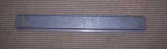
� When I first opened my package from Australia, I was a bit surprised to only find two � simple channel pieces. I guess I had expected something more complex, like the RV8 factory � piece, but considering how inexpensive the purchase was (about $25.00) I had little to � complain about. What makes them well worth their price is that they are bent to the � correct dimensions and that they are made from galvanized steel. Keep in mind that the � zinc fumes produced from welding galvanized metal can make you very, very sick and the � appropriate organic respirator or preferably a forced-air respirator should be worn. �
��
�
� To get there, a bit of "tin-smithing" is required. The first step is to cut one end of the � channel along each fold and bend back each of the resulting three tabs at a 90 degree angle. � How far back you cut is up to you, but I wanted the center tab to be long enough to wrap � over the central cross-member. After the length of channel is welded into place, the top � tab can be hammered down over the top of the cross-member and welded in place. I use the � generic term "weld", but its up to you to decide if you wish to spot, plug or stitch weld � the parts in place. Because I have a MIG welder, I'll be spot-welding these in place, with � the addition of structural epoxy between welds to keep water intrusion to a minimum. The � next step is to measure between the cross-member and the base of the spring perch. Mark a � line on the channel at this distance from the point where the three tabs start. The material � from this line to the untouched end of the channel will have to be cut and shaped to "box-in" � and wrap around the spring perch. There are a number of different ways to do this, and my way � may not be the best way.�
� �
�
� �
�
� As with any other bodywork, you'll have to remove some undercoating before you begin, as well � as the seats and carpeting, if you wish to avoid MGB Flambé. �
�
�
�
�
| �
Enjoying this article? Our magazine is funded through the generous support of readers like you! � To contribute to our operating budget, please click here and follow the instructions. � (Suggested contribution is twenty bucks per year. Feel free to give more!)� |
� As I mentioned earlier, the RV8 engineers also felt that this was a potential weak-spot, � and so they designed a load-bearing member that runs the same span. It also allows the � use of anti-tramp bars and handles the extra twisting load they introduce. If you are � tied into a good RV8 or British Motor Heritage supplier, you can buy the RV8 factory � part. If you are handy with a sheet-metal brake, you can make yourself a new structural � piece. If you are like the rest of us, you can send off some money to Adrian Akhurst in � Australia, and he will make you a set. I chose the last method, and the rest of the � article will cover that installation, though I suspect that the other two methods will � follow a similar enough process.�
� As each MGB is a little different than the next, I will intentionally omit dimensions. � For this project, they are easy enough to measure on your own vehicle.�
� When I first opened my package from Australia, I was a bit surprised to only find two � simple channel pieces. I guess I had expected something more complex, like the RV8 factory � piece, but considering how inexpensive the purchase was (about $25.00) I had little to � complain about. What makes them well worth their price is that they are bent to the � correct dimensions and that they are made from galvanized steel. Keep in mind that the � zinc fumes produced from welding galvanized metal can make you very, very sick and the � appropriate organic respirator or preferably a forced-air respirator should be worn. �
�
�
 � �
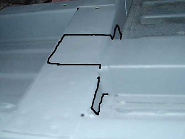
� When I held the parts up to the car, they seemed far longer than necessary, and it wasn't � obvious to me how I would attach them at their ends to the spring perch and cross-member. � A quick e-mail to Adrian resulted in a series of pictures that explained what I needed to � do, far better than words alone could have done.� | �
� | 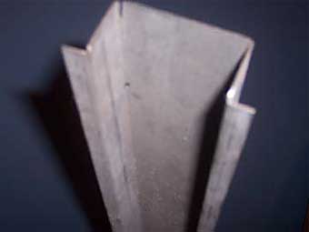 | �
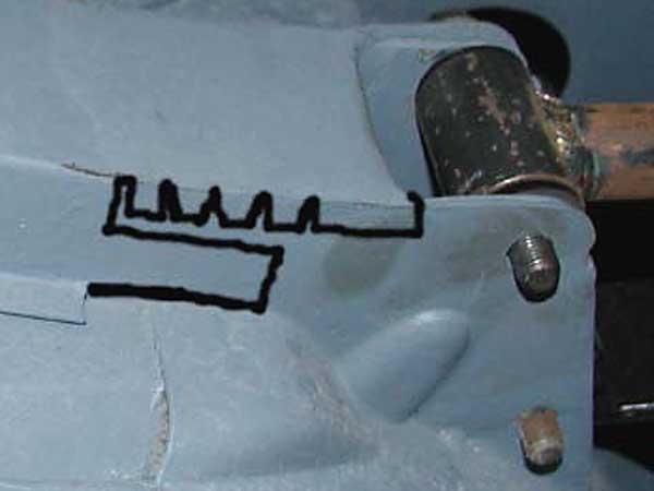
� To get there, a bit of "tin-smithing" is required. The first step is to cut one end of the � channel along each fold and bend back each of the resulting three tabs at a 90 degree angle. � How far back you cut is up to you, but I wanted the center tab to be long enough to wrap � over the central cross-member. After the length of channel is welded into place, the top � tab can be hammered down over the top of the cross-member and welded in place. I use the � generic term "weld", but its up to you to decide if you wish to spot, plug or stitch weld � the parts in place. Because I have a MIG welder, I'll be spot-welding these in place, with � the addition of structural epoxy between welds to keep water intrusion to a minimum. The � next step is to measure between the cross-member and the base of the spring perch. Mark a � line on the channel at this distance from the point where the three tabs start. The material � from this line to the untouched end of the channel will have to be cut and shaped to "box-in" � and wrap around the spring perch. There are a number of different ways to do this, and my way � may not be the best way.�
�
�
�
�
� As with any other bodywork, you'll have to remove some undercoating before you begin, as well � as the seats and carpeting, if you wish to avoid MGB Flambé. �
�
�
You should also take the appropriate measures to rustproof such as using weld-through primer �
on the interior surfaces, as well as one of the better rust-preventative top-coats, away from �
the welds. You can apply Waxoyl or similar gunk to the inside through a drill-hole after welding. �
On the outside, treat it like any other part that will be exposed to water and salt. And �
remember what I said about welding through zinc! As you can infer from the pictures, you �
have the option of adding anti-tramp bars to the concoction. Page 56 and 57 of Roger Williams' �
"How to Improve MGB, MGC & MGB V8" give detailed plans for making a set of your own �
reinforcements along with many pictures of the one on the RV8. His plans also account for �
anti-tramp bars. �
� You can also visit "The Autoist", Tony Barnhill at his web site and see his take on these parts, � which he calls "top hats." His web site is: www.theautoist.com.�
� Adrian Akhurst makes a lot of other goodies, including a Panhard rod and remote oil-filter � bracket that I'll review in a future issue. He can be contacted at: mgadel@senet.com.au. � Shipping costs from Oz are a bit pricey, so consider a bulk-buy for your local club to distribute � the pain. Now get out there and drive! �
� Disclaimer: This page was researched and written by James Jewell. Views expressed are those of � the author, and are provided without warrantee or guarantee. Apply at your own risk.�
�
�
� You can also visit "The Autoist", Tony Barnhill at his web site and see his take on these parts, � which he calls "top hats." His web site is: www.theautoist.com.�
� Adrian Akhurst makes a lot of other goodies, including a Panhard rod and remote oil-filter � bracket that I'll review in a future issue. He can be contacted at: mgadel@senet.com.au. � Shipping costs from Oz are a bit pricey, so consider a bulk-buy for your local club to distribute � the pain. Now get out there and drive! �
� Disclaimer: This page was researched and written by James Jewell. Views expressed are those of � the author, and are provided without warrantee or guarantee. Apply at your own risk.�