
� �
The New Buick Aluminum Engine
�| by: | J.D. Turlay, E.H. Holtzkemper, and C.G. Studaker |
| Buick Motor Division General Motors Corporation Flint, Michigan |
� re-published by permission in BritishV8 Magazine, Volume XVI Issue 2, October 2008�
�INTRODUCTION
��
The introduction of the new Special for 1961 was the result of a �
re-evaluation of the traditional Buick position in the overall car �
market. With this new concept of a smaller, fine car came the opportunity �
for the Engineering Department to start with a "clean sheet of paper", �
not encumbered with the requirements of utilizing existing tooling or �
components.�
�
It was recognized early that to make the necessary gains in fuel economy �
so important to the customer and yet maintain a level of performance �
acceptable to the discriminating car buyer, weight would be a critical �
factor. The decision to design an engine around major aluminum castings �
was the outgrowth of this realization, due not only to its direct effect �
upon overall car weight, but also it's effect upon the weight of other �
chassis components. By taking advantage of this overall weight reduction, �
engine displacement could be held at a minimum for a given level of �
performance with consequent advantage in both manufacturing and operating �
economies.�
�
The application of aluminum in engine design is far from new and the �
majority of engines on the market today have utilized this material �
in some form for many years. An aluminum hi-performance V-8 engine was �
designed and built at Buick to power the famous XP-300 and LeSabre �
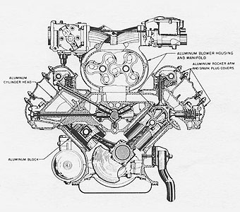
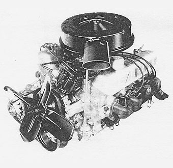
experimental cars of the early 1950's (Figure 1). The new Special engine, �
however, is the first mass produced aluminum V-8 engine to be used in an �
American-built passenger car.�
 | �
� |  | �
| Figure 1 EXPERIMENTAL XP-300 ALUMINUM ENGINE | �
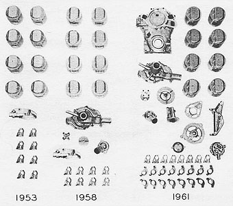
� | Figure 2 EVOLUTION OF ALUMINUM IN BUICK V-8 ENGINE | �
�
Recognizing the advantage of aluminum in making possible both weight and �
cost savings, a gradual evolution has been taking place at Buick since �
the introduction of the present line of cast iron V-8 engines in 1953 �
(Figure 2). Aluminum pistons, rocker arm shaft brackets and oil filter �
base were incorporated in the original design. The water pump cover, �
water manifold, water outlet and timing chain cover were designed for �
die casting in aluminum; however, economic considerations did not permit �
their adoption at that time. All, except the water manifold, have since �
been re-evaluated as aluminum die castings and released for production: �
the water outlet in 1955, the water pump cover in 1957, and the timing �
chain cover in 1958. In addition, the 1961 large Buick engines include �
die cast rocker arms, water pump impeller, generator end frames, generator �
bracket, fan spacer, fuel pump dome and body to further supplement the �
conversion to lightweight aluminum castings. The experience gained through �
the use of the above parts, especially those exposed to the coolant, gave �
us the necessary background to embark on a program of extending the use �
of aluminum to the major castings of the Special engine: namely, the �
cylinder block, cylinder heads and intake manifold. �
�
In addition to the above experience, we have drawn heavily on the �
background of knowledge in the use of aluminum for major engine components �
available from the Power Development Section of the Engineering Staff �
Division, General Motors Technical Center. They have been engaged in �
extensive research and development in this field since 1951 and their �
assistance has been invaluable. Prototype engines for this program�
originated with them, with Buick assisting by serving as prime supplier �
to gain further experience. The production design was started at Buick �
in December of 1958 and much of the experience obtained from the �
prototype program applied directly to the engine being covered by �
this paper.�
�
There has been much discussion regarding the corrosion characteristics �
of aluminum when used in critical locations connected with the engine �
cooling system. Our experience with the water pump cover, timing chain �
cover and water outlet has shown that with proper care in the selection �
of the alloy used, in meeting the design requirements, and in careful �
manufacturing control, corrosion does not become a field problem. All �
of these parts are cast of GM-4097M alloy containing 11.0 to 13.0 �
percent, silicon and less than one percent copper for excellent corrosion �
resistance.�
GENERAL DESCRIPTION
��
An eight cylinder V-8 engine was chosen to power the new Buick Special due �
to its inherent advantages:
�
1. Small package size.
�
2. Smoothness of operation.
�
3. Rigid construction.
�
4. Excellent output characteristics and
�
5. Light weight.
�
It was felt that no compromise in any of the foregoing could be tolerated �
and still produce a vehicle of the quality desired by our customers. �
�
In view of the projected overall car weight of approximately 2700 pounds, �
a displacement of 215 cubic inches was chosen to provide for excellent �
economy characteristics while giving the driver the nimbleness he has come �
to expect in an American-built automobile. This displacement was obtained �
with a bore of 3.500" and a stroke of 2.800" for a stroke-bore ratio of �
0.8, the same as the original 322 cubic inch Buick V8 engine. �
�
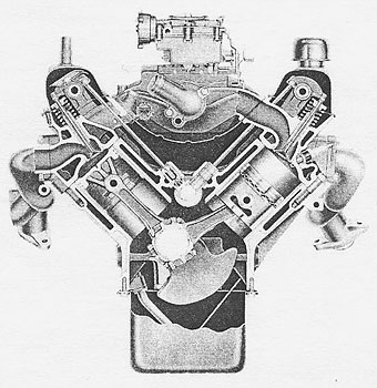
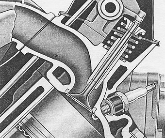
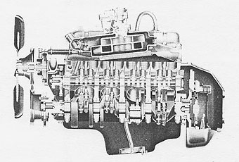
The overall engine compactness is readily apparent from a cross section of �
the engine (Figure 3) which clearly shows the functional use of all available �
space within the engine outline. Exhaust manifolds are neatly tucked in along �
the cylinder banks to reduce the overall engine width. The intake manifold is �
recessed in the "V" of the cylinder heads as close to the curved lifter �
compartment cover as possible to reduce overall engine height.�
 | �
� |  | �
| Figure 3 TRANSVERSE CROSS-SECTION OF BUICK ALUMINUM V-8 | �
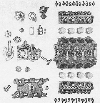
� | Figure 4 ALUMINUM COMPONENTS OF 215 ENGINE | �
�
Aluminum castings were utilized wherever possible (Figure 4) in the interest �
of maximizing weight saving. The cylinder block and cylinder heads are made �
by the semi-permanent mold process due to the necessity for sand water jacket �
and port cores. The intake manifold is made as a sand casting. Die castings �
include such components as: timing chain cover, water pump cover, water pump �
impeller, water outlet, flywheel housing, oil pump cover, rocker arms, rocker �
arm shaft brackets, distributor body, starter and generator end frames, �
carburetor throttle body, and oil pressure indicator switch housing. The �
pistons, as in most automotive engines in use today, continue as full permanent �
mold castings.�
�
All other engine components were carefully scrutinized to obtain a design �
providing for minimum weight while maintaining a high level of durability �
and structural rigidity.�
�
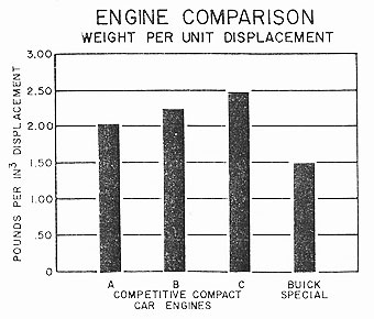
The final result of this weight-conscious approach to the design of the new �
Special engine is a total dry weight of 324 pounds or 1.50 pounds per cubic �
inch displacement (Figure 5). A comparison with several 1960 American-built �
compact car engines reveals that this weight per cubic inch ratio is far �
superior and is the only one with a value under two pounds per cubic inch �
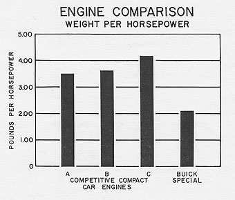
displacement. As an additional measure of the benefits of this concentrated �
attack on the weight problem, a comparison of the performance level in terms �
of pounds per horsepower output reveals a figure of 2.09 for this engine as �
compared to 3.50 for the nearest competitor.�
 | �
� |  | �
| Figure 5 COMPARISON OF WEIGHT PER UNIT DISPLACEMENT | �
� | Figure 6 COMPARISON OF WEIGHT PER HORSEPOWER OUTPUT | �
COMBUSTION CHAMBER
��
The American car buyer is becoming increasingly more critical of car �
operating costs and for this reason it was established that the Special �
should operate on regular gas. To accomplish this and still provide maximum �
utilization of the regular grade fuels available, careful attention was �
given the selection of a combustion chamber for the new engine.�
�
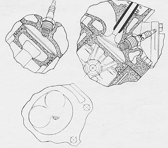
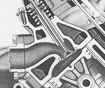
The combustion chamber finally chosen was formed by a slanted, elongated �
saucer shape in the cylinder head accompanied by a shallow circular depression �
in the piston dome (Figure 7). Piston coverage of 15 percent is provided �
by a 0.35" wide land around the top of the piston adding to the turbulence �
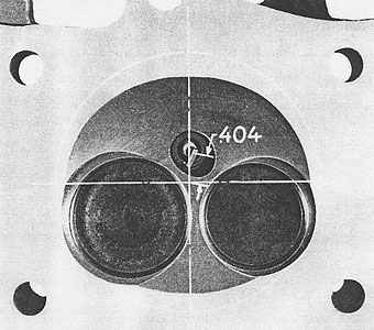
of the swirling fuel-air mixture leaving the slightly offset inlet port. �
The spark plug is centrally located, being only 0.404 inches from the �
cylinder centerline (Figure 8) which results in a short, uniform flame �
travel to all parts of the chamber.�
 | �
� |  | �
| Figure 7 COMBUSTION CHAMBER | �
� | Figure 8 SPARK PLUG LOCATION | �
� The new design combines the low surface-to-volume ratio advantage of the � hemispherical chamber with the turbulence of the wedge-type chamber for � excellent mechanical octane characteristics. This permits operation with � deposits at a compression ratio of 8.8 to 1 on 92 Research octane fuel � without trace knock. In addition, this chamber includes an in-line valve� arrangement with minimum shrouding of both inlet and exhaust valves � providing a high degree of breathing efficiency.�
�SERVICE
��
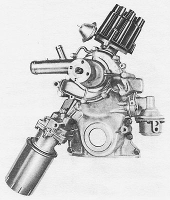
Serviceability was of prime importance in the overall engine arrangement �
and resulted in several interesting features. The ignition distributor is �
located in the timing chain cover at the front of the engine (Figure 9) �
eliminating the need for the average mechanic to double as a contortionist �
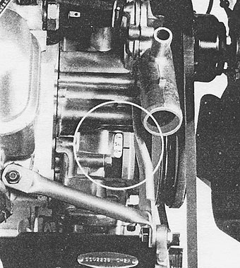
for even a simple point adjustment. The timing indicator, being cast �
integral as a part of the timing chain cover (Figure 10) is conveniently �
located in close proximately to the distributor, permitting the mechanic �
to accurately adjust the distributor and observe the timing point from �
the same position. �
�
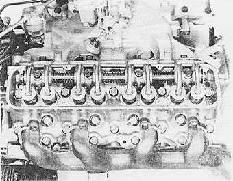
Spark plugs are all easily accessible (Figure 11) even with a full �
complement of accessories - including power steering and air conditioning. �
All cylinder head bolts may be reached with the rocker arm covers removed �
without disturbing the exhaust manifolds, also adding to the convenience �
of the Service Department should head removal ever be required. �
 | �
� |  | �
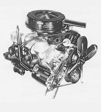
| Figure 9 RIGHT FRONT VIEW OF ENGINE | �
� | Figure 10 IGNITION TIMING INDICATOR | �
 | �
� |  | �
| Figure 11 ASSEMBLED CYLINDER HEAD | �
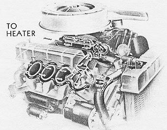
� | Figure 12 ENGINE COOLING SYSTEM | �
COOLING SYSTEM
��
A straight-through type cooling system is employed with the cylinder heads �
being in series with the cylinder block on their respective banks (Figure 12). �
Water enters the pump through a passage in the die cast water pump cover and �
passes through three holes near the hub of the six-vane die cast impeller. �
The rim of the impeller serves as a seal between the inlet and outlet sides �
of the water pump while a cast cavity in the front of the timing chain cover �
forms the rear surface of the pump. This construction permits the die casting �
of both the water pump and the timing chain covers and provides an efficient, �
low-cost water pump. �
�
From the outlet side of the pump, the water divides uniformly and enters the �
cylinder block through openings in front of each cylinder bank. After passing �
around the cylinder walls to the rear of the block, the flow is directed �
through passages in the top deck to the rear of the cylinder heads. From �
here the coolant travels forward through the head to an outlet at the front �
on the intake manifold mounting surface. At this point the water proceeds �
under the manifold proper to the rear and hence to the top of the manifold, �
forward around the carburetor mounting flange to the thermostat housing �
cavity, cast integral with the manifold.�
�
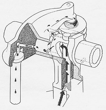
The thermostat by-pass is provided by an integrally-cast tube on the water �
outlet which registers with a hole drilled into the thermostat cavity of the �
intake manifold (Figure 13). A short rubber hose from this tube, in turn, �
connects with a similar inlet on the timing chain cover leading to a passage �
to the inlet side of the water pump. �
�
Water pump and fan speed ratio is 0.85 to 1 to provide adequate coolant flow �
with minimum power requirement and low level of fan noise.�
 | �
� |  | �
| Figure 13 THERMOSTAT BY-PASS AND WATER PUMP | �
� | Figure 14 FRONT COVER ASSEMBLY | �
LUBRICATION SYSTEM
��
The lubrication system centers around the front mounted oil pump (Figure 14) �
driven directly by the distributor. This necessitates the use of a non-submerged, �
external oil pump remote from the sump located near the center of the oil pan. �
�
The oil pump gear cavity is integral with and machined in the timing chain �
cover insuring correct alignment between the oil pump driving gear shaft and �
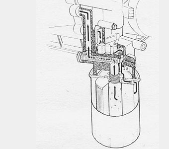
the distributor mounting hole (Figure 15). The oil pump cover is a separate �
die casting and serves as a mounting for the full flow, throw-away type oil �
filter cartridge, eliminating the need for a separate oil filter base. Both �
the oil pressure relief valve and the oil filter bypass valve are located in �
the pump cover to further consolidate functional components. A 30 mesh screen �
is located in series with the oil pressure relief valve to prevent stray �
chips and dirt from interfering with the operation of the plunger-type valve. �
 | �
� |  | �
| Figure 15 ENGINE OIL PUMP | �
� | Figure 16 ENGINE LUBRICATION | �
�
The oil pump intake is provided by a drilled hole down the right side of the �
cylinder block to the center main bearing bulkhead (Figure 16) on which the �
intake screen and housing assembly is mounted. A separate screen assembly, �
of 24 mesh, is located in the housing with a thin annulus of 0.050" thickness �
around the periphery to permit oil to pull over in the event the screen �
becomes plugged. �
�
As the incoming oil leaves the cylinder block it proceeds through passages in �
the timing chain cover to the pump cavity proper. A standpipe effect is �
attained on both the inlet and outlet sides of the pump to insure a sufficient �
reservoir of entrapped oil for reprime of the pump in the event the remainder �
of the system is drained. �
�
High pressure oil passes from the pump outlet into the pump cover, through the �
filter and back into the cover via the steel nipple cast in place for the filter �
mounting. Passages in the pump cover and timing chain cover, in turn, direct the �
oil to the high pressure galleries in the cylinder block. The oil pressure �
indicator light switch is mounted in the oil filter by-pass valve cap since this �
hole serves as part of the outlet passage for the high pressure oil to the block.�
�
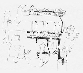
The high pressure oil distribution system consists of two main oil galleries �
drilled the length of the block and intersecting the valve lifter holes for �
approximately one-half the gallery diameter. This then supplies the lifters with �
oil at line pressure and insures an adequate supply of oil to the lifters at all �
times. �
�
Oil is supplied to the main and cam bearings by angled holes drilled from the �
top center of the main bearing bores to the right-hand main oil gallery. Connecting �
rod bearings are furnished oil in the conventional manner with holes drilled �
in the crankshaft.�
�
Full pressure overhead lubrication is supplied by a drilled hole intersecting �
the main oil gallery ahead of the front valve lifter boss on each bank. A cast �
depression in the base of the symmetrical rocker arm shaft bracket provides �
passage for the oil to the mounting bolt hole and thence to the rocker arm shafts �
(Figure 17). By taking the overhead oil from a point ahead of all lifters in the �
main galleries, a maximum amount of entrained air is bled off ahead of the lifters, �
resulting in better lifter performance. �
 | �
� |  | �
| Figure 17 OVERHEAD LUBRICATION | �
� | Figure 18 FRONT END LUBRICATION | �
�
Drilled holes are located in the shafts at each rocker arm location and are �
rotated toward the push rod ends of the rocker arms away from the high load point �
to permit a sufficient quantity of oil to escape for proper lubrication of the �
overhead mechanism. Strategically located lubricating grooves are broached in the �
rocker arm bores to provide a film of oil which is distributed by the oscillating �
action of the rocker arm. The push rod seat end of each rocker arm is supplied an �
adequate amount of oil by a hole drilled to the seat end from the rocker arm shaft �
bore. The valve tip end is lubricated by controlled oil flow along the rib section �
on the side of each rocker arm. A slot located in the rocker arm hub allows this�
oil to escape from the chamfer around the inside diameter of the hub and is located �
such that only the required portion of oil finds its way across the top of the arm �
and thence to the valve tip. Excess oil spills off the backside of the rocker arm �
away from the valve tip end. Since this arrangement effectively meters the amount �
of oil reaching the valve stems and guides, no auxiliary seals or shields are �
required.�
�
Oil for lubricating the distributor gears, fuel pump eccentric, timing chain and �
sprockets is supplied in an unusual manner. Leakage oil from the front cam bearing �
is trapped by the thrust flange and delivered through a drilled hole to the sprocket �
and eccentric keyway (Figure 18). A radial slot on the front side of the eccentric �
registers with the keyway and provides an outlet for the oil. In operation, oil is �
thrown radially from this slot to the distributor gear which in turn throws the oil �
onto the timing chain and fuel pump eccentric. This system lubricates all parts �
operating in the front cover without flooding the area, thus reducing the load on �
the front crankshaft seal. �
�
The front crankshaft oil seal is of the graphite impregnated rope type held in place �
in the front cover by a pressed-in steel retainer. A shelf on the inside of the �
timing chain cover reduces the direct flow of runoff oil into the seal area. In �
addition, a slinger mounted on the crankshaft extends over a lip on the seal �
retainer and effectively reduces the amount of oil reaching the seal proper.�
�
The rear main bearing oil seal is also of the graphite impregnated rope type, but �
of necessity, is split with one-half in the cylinder block and the other half in �
the rear main bearing cap. A slinger machined on the crankshaft ahead of the seal �
area operates in a groove machined in the cylinder block. The slinger groove is �
drained by a cast-in slot at the bottom and in addition is vented into the �
crankcase section by a hole drilled near the top. �
CYLINDER BLOCK
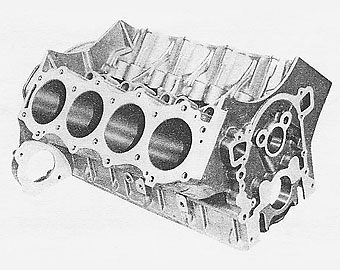
�� The cylinder block, being the largest individual structural component of � the engine, offered the greatest potential weight savings through the use � of aluminum (Figure 19). Semi-permanent mold castings were chosen to permit � use of conventional sand cores in forming the water jackets and lower � crankcase area of the cylinder block. All remaining exterior surfaces of � the casting are formed by metal die sections, resulting in an attractive � casting appearance and providing excellent physical properties for such � critical areas as the cylinder head surfaces.�
� | �
� |  | �
| Figure 19 CYLINDER BLOCK | �
� | Figure 20 CYLINDER SLEEVE AND BLOCK ASSEMBLY | �
�
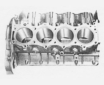
Long a major deterrent to the widespread use of aluminum cylinder blocks �
in the automotive industry has been the lack of an economical means of �
providing a satisfactory cylinder bore surface. This problem was overcome �
by the adoption of cast-in-place iron sleeves (Figure 20) thus eliminating �
the costly manufacturing complications of wet liners with their inherent �
sealing problems, pressed-in dry sleeves and accompanying increase in expensive �
precision machining requirements. �
�
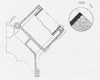
The outside diameter of the centrifugally-cast sleeve is machined with �
circumferential grooves having a pitch of 8 per inch and a depth of 0.010". �
These grooves form a very effective means for mechanically locking the sleeves �
in place. �
�
The cylinder block design incorporates the dropped pan rail (long a Buick engine �
feature) having the oil pan mounting surface 2.250 inches below the crankshaft �
centerline (Figure 21). This configuration provides flat oil pan mounting surface �
and also permits mounting the starter directly in the cylinder block for added �
rigidity. �
 | �
� |  | �
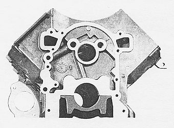
| Figure 21 FRONT OF CYLINDER BLOCK | �
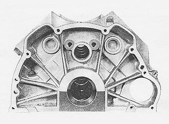
� | Figure 22 CYLINDER BLOCK FLYWHEEL HOUSING END | �
�
The mounting surface for both the Automatic and Synchromesh transmissions is provided �
by the well-ribbed deep-section flywheel housing end of the cylinder block �
(Figure 22). The effect of this deep block feature is an increase in the natural �
frequency of the engine-transmission assembly in vertical bending which provides �
a smoother, more nearly vibration free installation since this is well above the �
natural frequency response range of the rest of the vehicle. �
�
Two air inlets are provided in the flywheel housing of the cylinder block for the �
Air-Cooled Dual Path transmission. These inlets are covered by the die cast flywheel �
and clutch housings when the Synchromesh transmission is specified. �
�
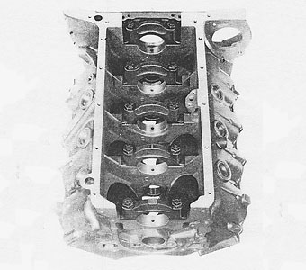
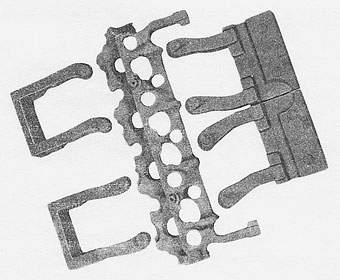
Cast iron main bearing caps are used with the aluminum cylinder block (Figure 23) �
and provide effective control of main bearing clearances throughout the operating �
range. The difference between the coefficient of expansion of aluminum and cast �
iron resulted in a problem in this area during the early stages of the development �
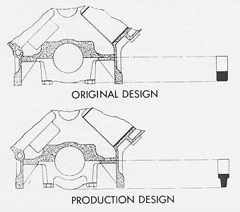
program. With the main bearing caps as originally designed (Figure 24), the higher�
expansion coefficient rate of the aluminum caused the horizontal clearance of the �
bearing to change at a greater rate than the vertical clearance with a change in �
temperature. Subsequent redesign of the main bearing caps, increasing the moment �
of inertia of the cap cross section by 67 percent, resulted in a significant �
reduction in the relative change between the vertical and horizontal bearing �
clearances. �
 | �
� |  | �
| Figure 23 BOTTOM VIEW OF CYLINDER BLOCK ASSEMBLY | �
� | Figure 24 MAIN BEARING CAP COMPARISON | �
 | �
� |  | �
| Figure 25 BOLT LOADING IN ALUMINUM | �
� | Figure 26 CYLINDER BLOCK WATER JACKET DEPTH | �
�
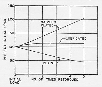
The bolt torque versus clamping load characteristics of aluminum threads presented �
an additional problem in the control of main bearing clearances. Repeated assembly �
of untreated bolts in the aluminum threads resulted in a substantial reduction in �
clamping load for a given bolt torque value (Figure 25). This loss in load caused �
a change in main bearing bore diameter between machining and engine assembly since �
the bearing caps are removed and reinstalled. An investigation into the merits of �
various thread treatments led to the development of a lubricant which gave uniform �
loading on the initial bolt installation as well as on reassembly at the same bolt �
torque. As a result the cylinder head, rocker arm shaft, and main bearing bolts are �
lubricated prior to the initial assembly since all are subjected to high loads and �
require uniform performance. �
�
A minimum thread engagement equivalent to twice the bolt diameter was adopted for �
all bolts threaded into aluminum to permit utilizing the load carrying capacities �
of the respective bolts. There has been no evidence of a loss in bolt loading in �
combination with the aluminum threads even after extensive operation of all types. �
�
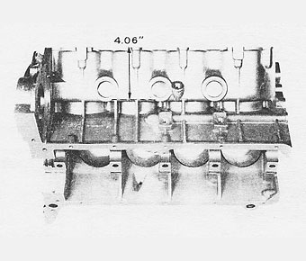
The depth of the water jacket in the cylinder block is only 4.06 inches as compared �
to an overall bore length of 5.56 inches (Figure 26). This results in a reduction �
in heat rejected to the cooling water and quicker warm-up while providing adequate �
cooling capacity. Only one cored opening through the cylinder head deck from the �
water jacket is provided at the rear of each bank resulting in a minimum of openings �
for potential cylinder head gasket water leaks (Figure 27). A cylinder head bolt �
pattern featuring five (5) bolts per cylinder was adopted due to the excellent �
performance of this pattern in our larger cast iron V-8 engines. �
�
A 0.015" thick aluminum-coated steel, beaded cylinder head gasket is used and is �
interchangeable between cylinder banks. Double beads are provided around the �
cylinder bores for added protection in these critical areas. �
 | �
� |  | �
| Figure 27 CYLINDER BLOCK AND HEAD GASKET | �
� | Figure 28 CYLINDER HEAD WATER JACKET AND PORT CORES | �
CYLINDER HEAD
��
The cylinder head is also a semi-permanent mold casting having dry sand water �
jacket and port cores. An interesting feature of the cylinder head is the use �
of a one-piece water jacket core (Figure 28) eliminating a pasted core sub-assembly �
and reducing the number of cores required from the core room. This one-piece �
core also results in more accurate control of wall sections and eliminates �
undesirable fins in the water jacket area. Port and water jacket cores may be �
assembled directly into the die eliminating the need for assembly fixtures. �
�
The water jacket core is designed to eliminate a maximum amount of unnecessary �
water while providing excellent cooling for such critical areas as inlet and �
exhaust valve seats, exhaust valve guides and spark plug bosses. The one-piece �
core design results in a triangular section having good structural strength �
characteristics for handling in the foundry.�
�
The elimination of the water jacketing over the inlet ports permits an open �
construction on this side of the cylinder head for a lightweight casting. Over �
head lubricating oil drains freely through this area to the cylinder block.�
 | �
� |  | �
| Figure 29 INLET PORT | �
� | Figure 30 EXHAUST PORT | �
�
Both inlet and exhaust ports (Figures 29 & 30) are streamlined to reduce �
to a minimum the resistance to flow of both the incoming fuel-air mixture and �
the departing exhaust gases. The exhaust port is kept short to reduce heat �
rejected to the cooling water and the elimination of the conventional exhaust �
crossover ports further minimizes the cooling requirements. �
�
Valve seat inserts of alloy cast iron are employed and are assembled into the �
cylinder head by a shrink fit process. Both valve and seat insert life have been �
very good, attributable in part to the excellent thermal conductivity of the �
aluminum head and the water jacketing around the valves. Separate, pressed-in-place �
alloy iron valve guides are also used to complete the cylinder head assembly. �
CRANKSHAFT
� �
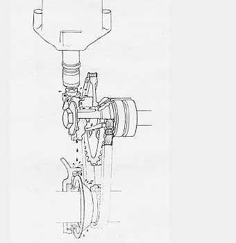
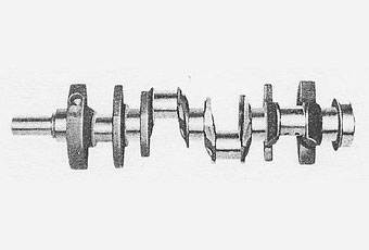
The crankshaft is an Arma-steel casting having the counterweight periphery �
and cheeks cast to size reducing casting weight and machining required �
(Figure 31). �
�
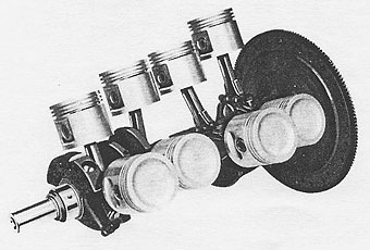
The counterweights are contoured for uniform clearance with the piston skirts, �
thus utilizing the most effective room available for counterweighting (Figure 32). �
In addition, the counterweights are oriented in the most advantageous plane for �
balancing the engine with the minimum amount of material. This design approach �
results in a finished crankshaft weighing only 38.4 pounds. The main bearing �
journal diameters are 2.300" and the crank pin diameter 2.000", which when �
coupled with 1.400" crank throw, results in an overlap of 0.75".�
�
The crankshaft end thrust is taken on a flange bearing at the center main bearing �
bulkhead (Figure 33). All main bearings are of steel-backed babbit material with �
a groove in the upper insert and plain lower inserts. The elimination of a groove �
in the lower insert increases load carrying capacity and also reduces oil pump �
flow requirements by effectively reducing leakage oil at the main bearing and �
partially metering the oil to the connecting rod bearings.�
 | �
� |  | �
| Figure 31 CRANKSHAFT | �
� | Figure 32 POWER TRAIN | �
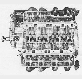
 | �
� |  | �
| Figure 33 LONGITUDINAL CROSS-SECTION OF ENGINE | �
� | Figure 34 PISTON AND CONNECTING ROD ASSEMBLY | �
CONNECTING ROD AND PISTON
��
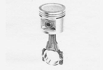
The connecting rods are made of SAE 1141 forged steel and have a center distance �
of 5.660" providing a conservative rod length to stroke ratio of 2.02 (Figure 34). �
Weight control is accurately maintained by the milling of weight bosses located �
at the connecting rod assembly center of gravity. The connecting rod bearings �
are also of steal backed babbit material.�
�
The piston is a one-piece aluminum alloy casting featuring the long-standing �
Buick practice of a full skirt, double trans-slot design. Windows are cast �
beneath the piston pin bosses to effectively divorce the skirt from the bosses �
in this area. Better dimensional control throughout the operating load range is �
obtained with this construction since the lower skirt is not as readily affected �
by pin boss deflections. This piston, coupled with the 0.875" diameter piston �
pin pressed into the connecting rod small end, supplies a rugged structural �
starting point for the transmission of mechanical energy to the flywheel. �
�
Two 5/64" compression rings and one 3/16" steel rail oil ring are provided with �
the top compression ring and the oil control ring chrome plated.�
VALVE TRAIN AND DRIVE
��
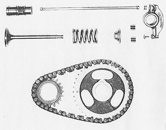
The alloy iron camshaft is driven by a 3/8" pitch chain through a sintered iron �
crankshaft sprocket and a cast iron camshaft sprocket (Figure 35). Hydraulic �
valve lifters are used with both Synchromesh and Automatic transmission engines. �
Push rods are made of 1/4" steel rod, upset and hardened at both ends. �
�
Die cast rocker arms similar to those introduced on the 1960 Buicks are employed �
to further extend the application of light metals to this engine. Inserts are �
installed at each end of the rocker arm with the ball seat for the push rod being �
of sintered iron and the valve-tip pad an upset steel insert. �
�
Inlet valve diameter is 1.500" and the exhaust valve diameter 1.3125". Both �
valve stem diameters are basically 0.340 inches with 0.0005 inches taper in the �
length of the stem - being smaller it the bottom. �
�
Enjoying this article? Our magazine is funded through the generous support of readers like you!
�
To contribute to our operating budget, please click here and follow the instructions.
�
(Suggested contribution is twenty bucks per year. Feel free to give more!)�
 | �
� |  | �
| Figure 35 VALVE TRAIN AND DRIVE | �
� | Figure 36 INLET MANIFOLD SECTIONS | �
INLET MANIFOLD AND CARBURETION
� �
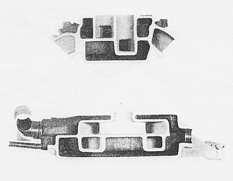
The intake manifold is the only completely sand cast component due to the �
complexity of coring in a V-8 manifold (Figure 36) and to the more flexible �
nature of the sand casting process.�
�
The branch size of the manifold was made as small as possible, consistent �
with good breathing characteristics, to provide a minimum manifold volume �
for instant response under changing load conditions. �
�
The intake manifold heat is provided by the water jacket through which all �
of the engine coolant flows. This results in a rapid rate of warm-up due to �
the excellent thermal conductivity characteristics of the aluminum. Another �
important advantage of this method of supplying manifold heat is the uniformity �
of temperatures of the mixture supplied to the individual cylinders. �
�
A two barrel carburetor is standard equipment on both Synchromesh and Automatic �
transmission engines and incorporates aluminum throttle body which, in �
conjunction with a metal carburetor to manifold gasket, provides excellent �
heat transfer characteristics. This construction reduces appreciably the �
tendency of the throttle valves and idle system to "ice up" under adverse �
atmospheric conditions. �
FUEL SYSTEM
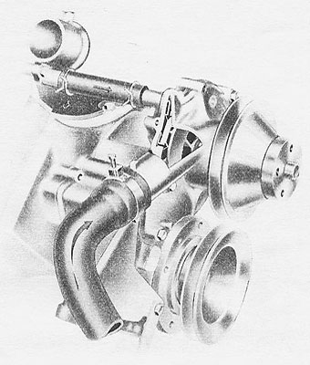
�� The fuel pump is mounted low on the loft side of the front cover (Figure 37) � and driven by a sintered iron eccentric mounted on the camshaft. A glass bowl, � paper cartridge fuel filter is standard on all engines and is mounted near the � carburetor to prevent foreign material from entering the critical needle seat or � jet areas. Metal lines are used between the carburetor and the fuel pump with � metal and rubber lines between the fuel pump and tank.�
� | �
� | 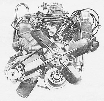 | �
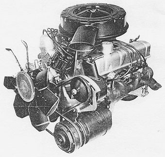
| Figure 37 LEFT FRONT VIEW OF ENGINE | �
� | Figure 38 FRONT VIEW OF ENGINE | �
EXHAUST MANIFOLDS
��
The cast iron exhaust manifolds have passages with gradually increasing �
cross-sectional areas to minimize resistance to flow of the burned gases.�
�
The right manifold incorporates a heat stove, which in conjunction with a �
stainless steel tube running through the manifold proper, supplies heated �
air to actuate the carburetor automatic choke. No heat valve with its potential �
sticking or rattle problem is used since the intake manifold is water-heated.�
�
A ball-type flange is used at the exhaust manifold to pipe junction, eliminating �
the need for a separate gasket and also providing flexibility for proper alignment �
of the exhaust system at this point.�
ELECTRICAL
�� The coil is mounted on the intake manifold forward of the carburetor in close � proximity to the distributor (Figure 38), resulting in a short high-voltage lead � wire for minimum voltage loss. The resistor type spark plug wires are held in place � with plastic clips attached to a bracket on each rocker arm cover. Extended reach � AC 45FFS spark plugs are used with a thread length of 1/2".�
�ENGINE VENTILATION
�� Engine ventilation inlet air is provided by a combination breather and filter cap � in the left rocker arm cover. The outlet for crankcase gases is provided by a � ventilator pipe in the right rocker arm cover, which extends down into an area � below the pan rail near the fore and aft centerline of the engine. A baffle is � mounted on two rocker arm shaft brackets beneath the outlet pipe (Figure 39) � preventing oil from splashing out the breather pipe and also providing a relatively � low velocity area for entrained oil to separate from the departing crankcase gases.�
� | �
� |  | �
| Figure 39 TOP VIEW OF ENGINE WITH COVERS REMOVED | �
� | Figure 40 ACCESSORY MOUNTINGS | �
ENGINE COVERS
� �
Valve rocker arm covers are of stamped steel, zinc plated for rust resistance and �
to further accentuate the appearance of the unpainted aluminum components. Right �
and left cover stampings are basically the same with the assemblies modified to �
take the ventilator breather cap in the left cover and the ventilator pipe in the �
right cover. �
�
The lifter compartment cover is formed by the intake manifold gasket extending �
across under the manifold proper and lengthwise to vertical walls at the front �
and rear of the cylinder block. Rubber seals are installed between the gasket �
and cylinder block at the end walls with a hardened steel clamp installed over �
the gasket. The clamp arc is designed to provide a uniform load on the gasket �
when torqued to the specified limits. �
OIL PAN
�� The oil pan is also a zinc plated steel stamping with the major sump area located � near the fore-and-aft centerline of the engine as dictated by chassis installation � requirements. �
�ACCESSORY MOUNTINGS
� �
The accessory mountings with a new engine design are usually left until �
all other components have been completely laid out. Consequently, the engine �
designer is concentrating on basic engine problems while the chassis and �
sheet metal designers are busy at work laying claim to all available space �
surrounding the engine. The end result is a frantic scramble to find �
suitable locations for mounting the generator, power steering pump, air �
conditioning compressor, etc. However, with engine compartment room at a �
premium in this installation, close cooperation between all design sections �
involved resulted in the maximum utilization of the space available.�
�
The generator is mounted low on the right-hand side of the engine directly �
in the fan blast for improved cooling. The rear end frame is attached �
directly to a boss on the exhaust manifold and the front supported by a �
simple triangular stamping bolted to the rear cover. An additional tubular �
brace is provided between the front pivot point and an end cylinder head �
bolt for increased mounting stiffness. A three-point drive is used with a �
single belt driving the generator and water pump.�
�
The power steering pump is mounted in front of the left cylinder head �
(Figure 40) with the rear bracket bolted to bosses provided on the head �
and the front bracket attached to the timing chain cover. �
�
The air conditioning compressor is mounted low on the left side of the �
engine with the rear mounting attached directly to the cylinder block. �
The front mounting bracket is shared with the power steering pump on �
those cars equipped with both, or is a similar but simplified bracket on �
non-power steering air conditioned cars. �
�
Both the power steering pump and air conditioning compressor are driven �
by a two-point drive with the belts going directly from the crankshaft �
pulleys to the individual accessory pulleys. Each accessory is adjustable �
to provide for belt tightening. �
�
These accessory mountings, being attached directly to the basic engine �
wherever possible, result in a rigid, vibration-free assembly so essential �
with the reduced mass of the aluminum engine. �
TEST RESULTS
��
During this development program experimental and initial production engines �
underwent over 10,000 hours of various dynamometer testing and 1,000,000 miles �
of operation in test cars prior to actual announcement to the public. No major �
engine failures occurred throughout this extensive development program attesting �
to the durability of this sturdy, yet lightweight engine.�
�
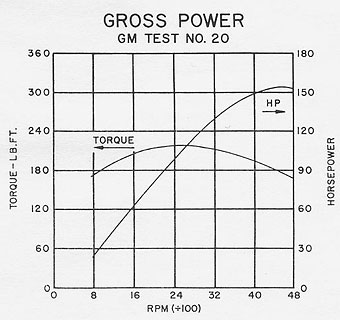
The adequate valve sizes in conjunction with the streamlined ports and manifolds �
result in an engine output curve giving excellent mid-range torque while �
maintaining a high level of horsepower output at speeds above 4000 R.P.M. �
(Figure 41). On a gross output basis, the engine is rated at 220 lb.-ft. �
torque at 2400 R.P.M. and 155 horsepower at 4600 R.P.M.�
�
�
Figure 41�
�
ENGINE OUTPUT - GM TEST NO. 20�
OPTIONAL ENGINES
�� An optional engine including a four barrel carburetor and a compression ratio � of 10.25 to 1 is available for those applications requiring an even higher � level of performance. This option increases the maximum torque output of the � engine to 230 lb.-ft. at 2800 R.P.M. and the horsepower to 185 at 4800 R.P.M., � also on a gross output basis. �
�CONCLUSIONS
� �
As a result of the experience gained during this development program as well as �
production experience to date, we feel the following conclusions to be important.�
�
1. A pronounced weight savings has been made through the extensive use of aluminum �
in this engine with no loss in engine output or durability.�
�
2. The basic goals of a quiet, durable, yet responsive engine have been attained �
by careful design consideration when combining the light weight of aluminum with �
the structural and wear characteristics of cast iron in critical areas.�
�
3. Normal care of the cooling system has been found to be entirely adequate in �
the control of corrosion in this aluminum engine. �
�
4. Engineering problems connected with an aluminum passenger car engine have been �
satisfactorily overcome and the further extension of aluminum to future engines �
will be governed primarily by economic considerations. �
APPENDIX
�GENERAL SPECIFICATIONS
�| Bore, In. | 3.50 | |
| Stroke, In. | 2.80 | |
| Displacement, Cu.In. | 215 | |
| Numbering System, Front to Rear | ||
| Left Bank | 1-3-5-7 | |
| Right Bank | 2-4-6-8 | |
| Firing Order | 1-8-4-3-6-5-7-2 | |
| Compression Ratio | 8.8-1 | |
| Crankshaft Main Bearing Diameter, In. | 2.300 | |
| Crankpin Journal Diameter, In. | 2.000 | |
| Connecting Rod Length, Center to Center, In. | 5.66 | |
| Rocker Arm Ratio | 1.6-1 | |
| Type of Lifters | Hydraulic | |
| Valve Spring Load, Lb. | ||
| Valve Closed | 64 | |
| Valve Open | 164 | |
| Valve Lift, In. | ||
| Inlet | 0.383 | |
| Exhaust | 0.383 | |
| Valve Head Diameter, In. | ||
| Inlet | 1.500 | |
| Exhaust | 1.3125 | |
| Valve Timing | ||
| Inlet Opens. Deg. BTC | 29 | |
| Inlet Closes, Deg. ABC | 71 | |
| Exhaust Opens, Deg. BBC | 67 | |
| Exhaust Closes, Deg. ATC | 33 | |
| Timing Point | Valve 0.004 In. Off Seat | |
| Engine Oil Pressure, Maximum P.S.I. | 33 | |
| Crankcase Oil Capacity, Qt. | 4 | |