
�
�
� Photo 1: Jeff Schlemmer Testing His Brakes
� �
� by: Jeff Schlemmer, proprietor of Advanced Distributors, LLC�
� (Editor's note: please make sure you read and fully understand the disclaimer � at the end of this article. Brake system performance is absolutely critical � to the safe operation of any car. Modifications that suit one owner or � application may be very dangerous in a slightly different application.) �
� I just knew that there must be a way to modify the stock braking system on � an MGB to provide better stopping power without having to purchase new � calipers and larger rotors. I have 205/50R15 racing compound tires, and they � offer plenty of stopping traction. Even with a fresh and complete rebuild,� the stock brakes in combination with braided-steel hoses and all new lines � just didn't offer the pressure and feel that I wanted. Mind you, I have a � Mark II (1971) MGB with non-servo dual line brakes. I don't want the soft � feel of power brakes, but I also don't want to have to use both feet to lock � them up! �
�
�
� Photo 1: Jeff Schlemmer Testing His Brakes
�
The Ultimate $15 MGB Brake Upgrade
� as published in British V8 Newsletter, Volume XIV Issue 3, December 2006�� by: Jeff Schlemmer, proprietor of Advanced Distributors, LLC�
� (Editor's note: please make sure you read and fully understand the disclaimer � at the end of this article. Brake system performance is absolutely critical � to the safe operation of any car. Modifications that suit one owner or � application may be very dangerous in a slightly different application.) �
� I just knew that there must be a way to modify the stock braking system on � an MGB to provide better stopping power without having to purchase new � calipers and larger rotors. I have 205/50R15 racing compound tires, and they � offer plenty of stopping traction. Even with a fresh and complete rebuild,� the stock brakes in combination with braided-steel hoses and all new lines � just didn't offer the pressure and feel that I wanted. Mind you, I have a � Mark II (1971) MGB with non-servo dual line brakes. I don't want the soft � feel of power brakes, but I also don't want to have to use both feet to lock � them up! �

�
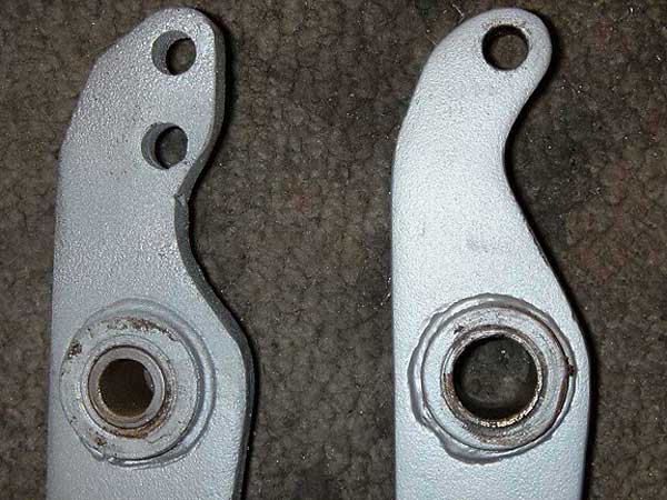
Photo 2 illustrates how I modified an MGB master cylinder bracket (or �
"brake box") to achieve thirty percent more braking power with the same �
pedal pressure. You can see the modified brake box on the left. Notice �
how a plate has been welded to the front surface of the box to relocate �
the master cylinder 1/2" lower than stock. Welding the plate to this side �
of the brake box was important. The idea was to lower the mounting of the �
master cylinder without changing its mounting plane. �
��

� Photo 2: Modified MGB Master Cylinder Bracket (at left) and Unmodified Bracket (at right)� �
�
�
�
�
� Photo 2: Modified MGB Master Cylinder Bracket (at left) and Unmodified Bracket (at right)�
�
�
I selected a master cylinder mounting plate from www.speedwaymotors.com �
(part number 916-41025) for about $15, but you could make your own �
relatively easily. The plate was made from 3/16" thick cold rolled steel, �
and came with pre-punched holes for mounting dual brake master cylinders �
and also one clutch master. I just cut it down and used the portion I needed. �
The plate actually wraps around both sides of the pedal support (shown �
projecting toward the viewer). I chose to MIG weld the plate all around its�
perimeter. �
�
��
� Photo 3: Modified MGB Brake Pedal (at left) and Unmodified Brake Pedal (at right)� �
� Photo 3 illustrates how I modified the pedal. Some material was welded on � to allow the same mounting depth for the master cylinder attaching point. � Then, a new pushrod attachment hole was drilled at a height calculated to � provide pushrod alignment. (Note: if you don't relocate the pushrod � attachment hole lower in the pedal, the master cylinder pushrod will� be misaligned and will certainly bind. Notice also that the brake light � switch was designed to contact the pedal higher than the newly drilled � pushrod attachment hole, so you mustn't trim off the top of the pedal. � Don't ask why I even bring that up!�
��
�
�
�
�
�
� Photo 3: Modified MGB Brake Pedal (at left) and Unmodified Brake Pedal (at right)�
� Photo 3 illustrates how I modified the pedal. Some material was welded on � to allow the same mounting depth for the master cylinder attaching point. � Then, a new pushrod attachment hole was drilled at a height calculated to � provide pushrod alignment. (Note: if you don't relocate the pushrod � attachment hole lower in the pedal, the master cylinder pushrod will� be misaligned and will certainly bind. Notice also that the brake light � switch was designed to contact the pedal higher than the newly drilled � pushrod attachment hole, so you mustn't trim off the top of the pedal. � Don't ask why I even bring that up!�
�
| �
Enjoying this article? Our magazine is funded through the generous support of readers like you! � To contribute to our operating budget, please click here and follow the instructions. � (Suggested contribution is twenty bucks per year. Feel free to give more!)� |
�
�
The relative position of pushrod attachment is what determines pedal ratio. �
Measure the distance from the center pivot of the brake pedal to the center �
of the footpad, and then divide by the distance from the pivot hole to the �
master cylinder pushrod attachment hole to calculate "pedal ratio." The total �
effect of this modification was to increase the pedal ratio from the stock �
ratio of 4.35:1 up to a new ratio of about 6:1. It would be very easy to do �
locate the master cylinder and attachment hole even lower to produce an even �
greater ratio, which would result in even easier braking effort. The "feel" �
of this change could be best described as half way between stock brakes and �
power brakes. The pedal is much more responsive and lighter in feel, but not �
soft by any means. Pressure at the calipers is increased from a stock 1227psi �
to a nice 1644psi. I don't have any issues with wheel lock-up and it performs �
flawlessly. This could be a do-it-yourself job for nearly anyone with a MIG �
welder and the knowledge to use it. It can be accomplished for about $15, and �
it provides the cold stopping power you would expect from a very expensive �
"big brake" upgrade kit.�
� Drive fast & take chances!�
� Disclaimer: This page was researched and written by Jeff Schlemmer. Views expressed � are those of the author, and are provided without warrantee or guarantee. Apply at your � own risk. Please especially note that this article suggests a deliberate compromise � between (longer) brake pedal travel and (increased) braking force as can be accomplished � by increasing mechanical advantage in the pedal assembly. Although Jeff reports excellent � results in his particular application, this compromise may be ill-advised for your � application. For example, you might find an insufficient safety margin of pedal height � remains for dealing with a ruptured brake line, heat-related brake "fade", or air trapped � in the brake system. There could be other un-foreseen safety problems. For further � information we recommend "Brake Systems - OEM and Racing Brake Technology" � by Mike Mavrigian and Larry Carleys and "Brake Handbook" by Fred Puhn.�
� Brakes are critically important safety equipment. If you're uncomfortable working on � brake components take the work to a qualified professional. �
� Photos by Jeff Schlemmer. All rights reserved. �
�
�
� Drive fast & take chances!�
� Disclaimer: This page was researched and written by Jeff Schlemmer. Views expressed � are those of the author, and are provided without warrantee or guarantee. Apply at your � own risk. Please especially note that this article suggests a deliberate compromise � between (longer) brake pedal travel and (increased) braking force as can be accomplished � by increasing mechanical advantage in the pedal assembly. Although Jeff reports excellent � results in his particular application, this compromise may be ill-advised for your � application. For example, you might find an insufficient safety margin of pedal height � remains for dealing with a ruptured brake line, heat-related brake "fade", or air trapped � in the brake system. There could be other un-foreseen safety problems. For further � information we recommend "Brake Systems - OEM and Racing Brake Technology" � by Mike Mavrigian and Larry Carleys and "Brake Handbook" by Fred Puhn.�
� Brakes are critically important safety equipment. If you're uncomfortable working on � brake components take the work to a qualified professional. �
� Photos by Jeff Schlemmer. All rights reserved. �